


11. OPTIONS AND PERIPHERAL EQUIPMENT
11 - 97
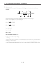
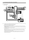
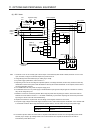
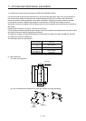
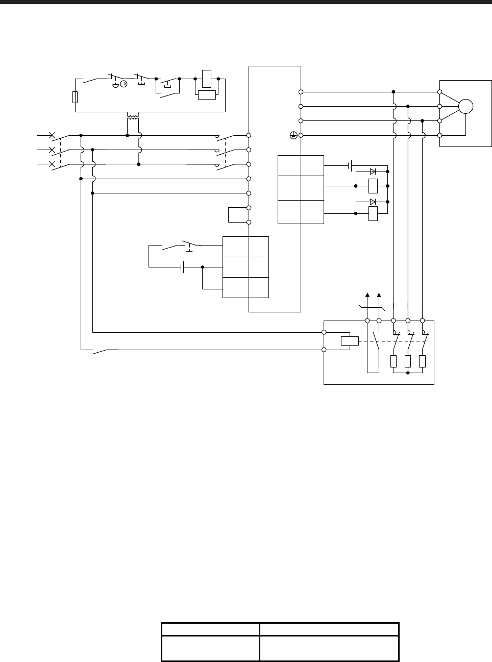
(b) 400 V class
Emergency
stop switch
L11
L21
U
V
W
U
V
W
E
M
Servo amplifier
Servo motor
L3
L2
L1
(Note 3)
Power
supply
13 U14 V W
External dynamic brake
a
b
(Note 1)
ALM15
DB
(Note 2,
10)
DOCOM
3
CN3
RA2
MCCB
Operation read
y
MC
ALM
RA1
OFF ON
MC
SK
RA1
RA2
MC
Dynamic brake
interlock
(Note 4)
(Note 5)
Main circuit
power supply
24 V DC (Note 6)
5
DICOM 10
EM2 20
DICOM
CN3
24 V DC (Note 6)
P3
P4
(Note 7)
(Note 8) Step-down
transformer
(Note 9)
Note 1. Terminals 13 and 14 are normally open contact outputs. If the external dynamic brake is seized, terminals 13 and 14 will
open. Therefore, configure an external sequence to prevent servo-on.
2.
A
ssign DB (Dynamic brake interlock) in [Pr. PD07] to [Pr. PD09].
3. For power supply specifications, refer to section 1.3.
4. Depending on the main circuit voltage and operation pattern, bus voltage decreases, and that may cause the forced stop
deceleration to shift to the dynamic brake deceleration. When dynamic brake deceleration is not required, slow the time to
turn off the magnetic contactor.
5. Turn off EM2 when the main power circuit power supply is off.
6. The illustration of the 24 V DC power supply is divided between input signal and output signal for convenience. However,
they can be configured by one.
7. Between P3 and P4 is connected by default. When using the power factor improving DC reactor, remove the short bar
between P3 and P4. Refer to section 11.11 for details. Additionally, a power factor improving DC reactor and power factor
improving AC reactor cannot be used simultaneously.
8. Stepdown transformer is required when the coil voltage of the magnetic contactor is 200 V class.
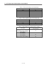
9. The power supply voltage of the inside magnet contactor for 400 V class external dynamic brake DBU-11K-4 and DBU-22K-
4 is restricted as follows. When using these external dynamic brakes, use them within the range of the power supply.
External dynamic brake Power supply voltage
DBU-11K-4
DBU-22K-4
1-phase 380 V AC to 463 V AC, 50
Hz/60 Hz
10. The external dynamic brake cannot be used for compliance with SEMI-F47 standard. Do not assign DB (Dynamic brake
interlock) in [Pr. PD07] to [Pr. PD09]. Failure to do so will cause the servo amplifier to become servo-off when an
instantaneous power failure occurs.