


11. OPTIONS AND PERIPHERAL EQUIPMENT
11 - 33
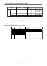
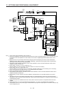
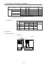
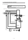
2) Control circuit terminal
POINT
Under tightening can cause a cable disconnection or malfunction. Over
tightening can cause a short circuit or malfunction due to damage to the screw
or the brake unit.
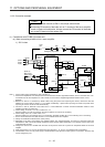
A
RES
PC
B
SD
BUE
C
MSG
SD
MSG
SD SD
Jumper
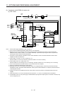
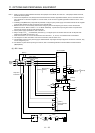
Terminal block
Insulator
Core
6 mm
Wire the stripped cable after twisting to prevent the cable
from becoming loose. In addition, do not solder it.
Screw size: M3
Tightening torque: 0.5 N•m to 0.6 N•m
Wire size: 0.3 mm
2
to 0.75 mm
2
Screw driver: Small flat-blade screwdriver
(Tip thickness: 0.4 mm/Tip width 2.5 mm)
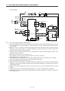
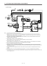
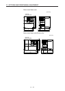
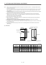
(b) Cables for connecting the servo amplifier and a distribution terminal block when connecting two sets
of the brake unit
Brake unit
Wire size
HIV wire [mm
2
]AWG
FR-BU2-15K 8 8
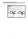
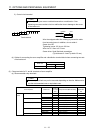
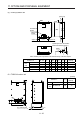
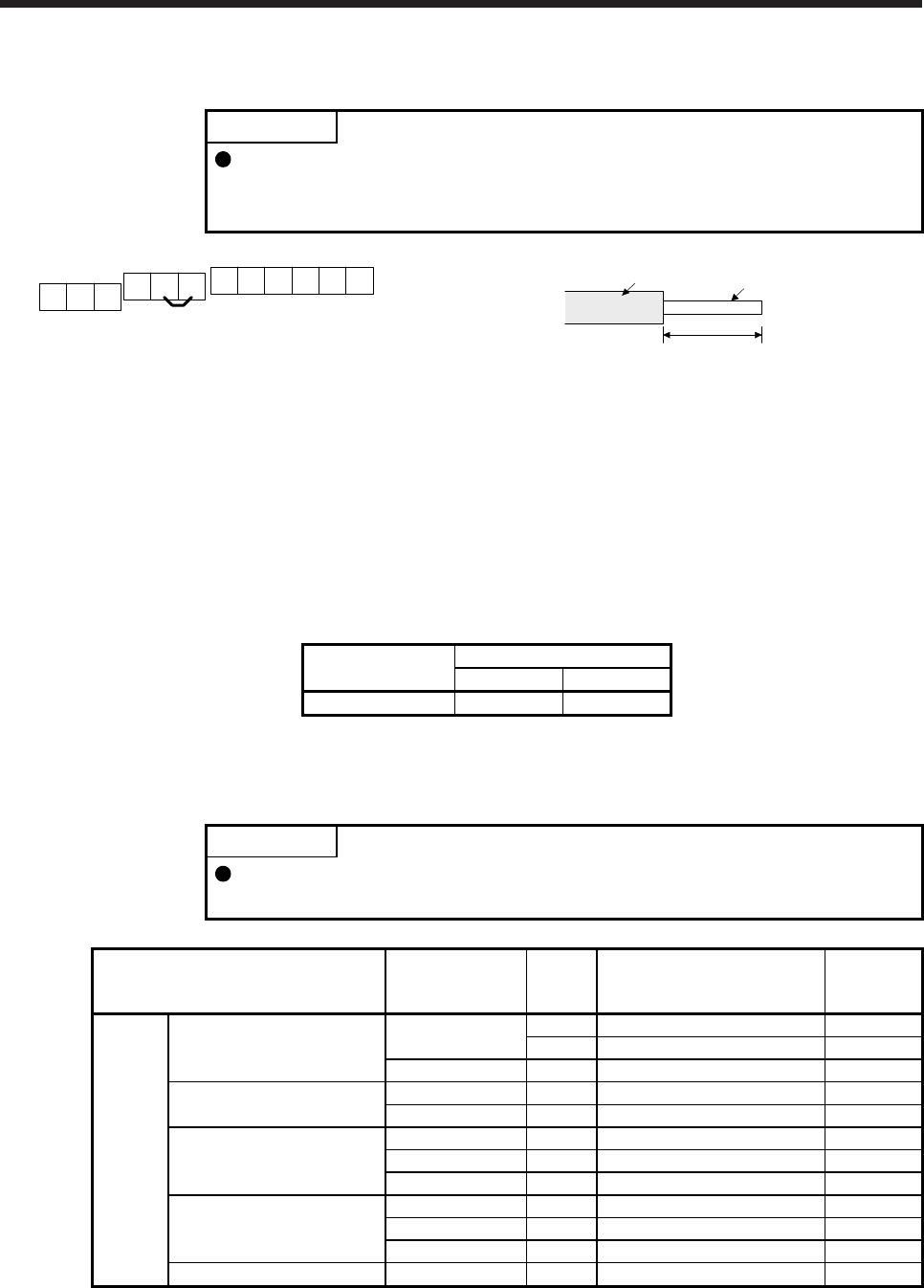
(5) Crimp terminals for P+ and N- terminals of servo amplifier
(a) Recommended crimp terminals
POINT
Some crimp terminals may not be mounted depending on the size. Make sure to
use the recommended ones or equivalent ones.
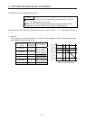
Servo amplifier Brake unit
Number of
connected
units
Crimp terminal (Manufacturer)
(Note 1)
Applicable
tool
200 V
class
MR-J4-500B(-RJ) FR-BU2-15K 1 FVD5.5-S4 (JST) a
2 8-4NS (JST) (Note 2) b
FR-BU2-30K 1 FVD5.5-S4 (JST) a
MR-J4-700B(-RJ) FR-BU2-15K 2 8-4NS (JST) (Note 2) b
FR-BU2-30K 1 FVD5.5-S4 (JST) a
MR-J4-11KB(-RJ) FR-BU2-15K 2 FVD8-6 (JST) c
FR-BU2-30K 1 FVD5.5-6 (JST) a
FR-BU2-55K 1 FVD14-6 (JST) d
MR-J4-15KB(-RJ) FR-BU2-15K 2 FVD8-6 (JST) c
FR-BU2-30K 1 FVD5.5-6 (JST) a
FR-BU2-55K 1 FVD14-6 (JST) d
MR-J4-22KB(-RJ) FR-BU2-55K 1 FVD14-8 (JST) d