15. USING A DIRECT DRIVE MOTOR
15 - 9
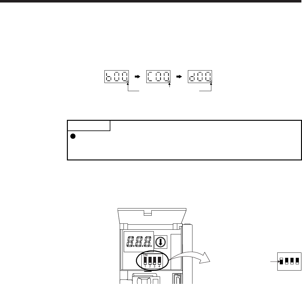
(c) State transition of the servo amplifier display (3-digit, 7-segment LED) at the magnetic pole detection
When the magnetic pole detection with MR Configurator2 is normally executed, the servo amplifier
display (3-digit, 7-segment LED) shows the state as below.
The decimal point flickers.
Servo-off status
During the
magnetic
pole detection
Magnetic pole
detection
completed
(Servo-on status)
(2) Preparation for the magnetic pole detection
POINT
When the test operation mode is selected with the test operation select switch
(SW2-1), the SSCNET III/H communication for the servo amplifier in the test
operation mode and the following servo amplifiers is blocked.
For the magnetic pole detection, use the test operation mode (positioning operation) of MR
Configurator2. Turn off the servo amplifier power, and set the test operation select switch (SW2-1) and
the disabling control axis switch (SW2-2, SW2-3, and SW2-4) as shown below. Turning on the power
enables the test operation mode.
Set SW2-1 to "ON (up)".
1
ON
2 3 4


