


1. FUNCTIONS AND CONFIGURATION
1 - 3
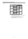
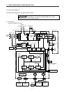
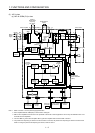
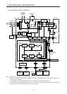
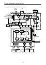
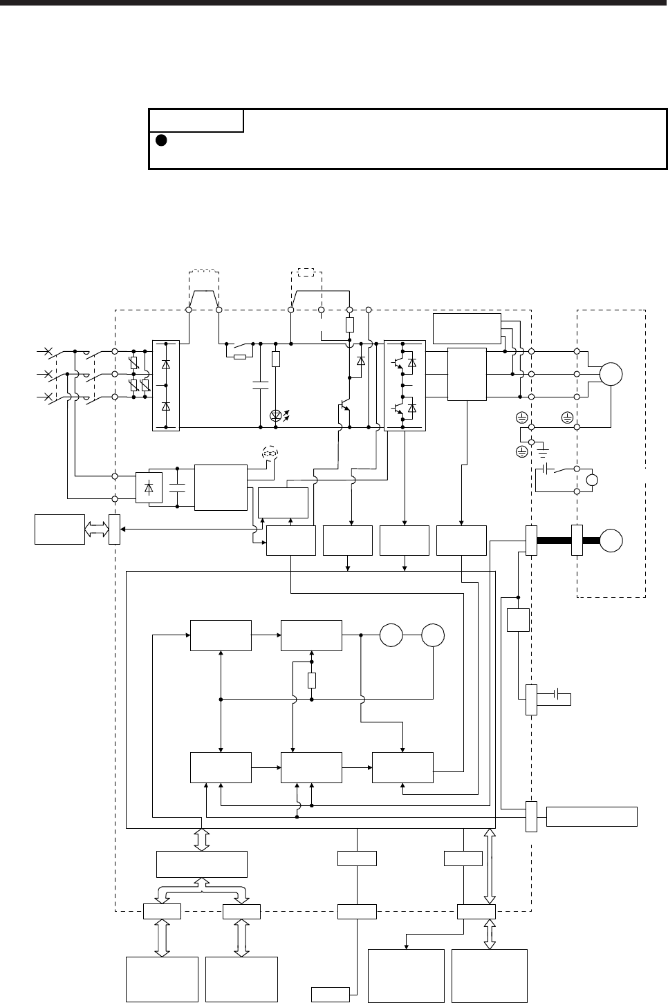
1.2 Function block diagram
The function block diagram of this servo is shown below.
POINT
The diagram shows for MR-J4-
_
B_-RJ as an example. MR-J4-
_
B_ servo
amplifier does not have CN2L connector.
(1) 200 V class
(a) MR-J4-500B(-RJ) or less
Model position
Current
control
Actual
position
control
Actual
speed
control
Virtual
motor
Virtual
encoder
L11
L21
Cooling fan
(Note 3)
Encoder
(Note 4)
N-CD
L3
L2
L1
Dynamic
brake
circuit
Power factor improving
DC reactor
Current
detection
Overcurrent
protection
Voltage
detection
(Note 2)
Power
supply
MCMCCB
Base
amplifier
STO
circuit
CN5
USB
USB
Personal
computer
Servo system
controller or
servo amplifier
Servo
amplifier
or cap
CN1A CN1B
D/A
Analog monitor
(2 channels)
Position
command
input
CN3
Servo amplifier
U
V
W
U
V
W
P3 P4
Diode
stack
Relay
P+
+
+
B
RA
24 V DC
B1
B2
Battery
(for absolute position
detection system)
CN4
STO
switch
Model speed Model torque
M
CN2
CN8
Control
circuit
power
supply
Model
position
control
Model
speed
control
I/F Control
Servo motor
CHARGE
lamp
Regene-
rative
TR
Current
encoder
Digital I/O
control
Regenerative
option
U U
U
Step-
down
circuit
Electromagnetic
brake
(Note 1)
(Note 5)
(Note 6)
CN2L
External encoder