


5. PARAMETERS
5 - 6
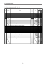
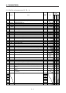
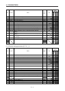
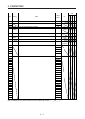
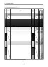
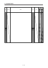
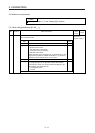
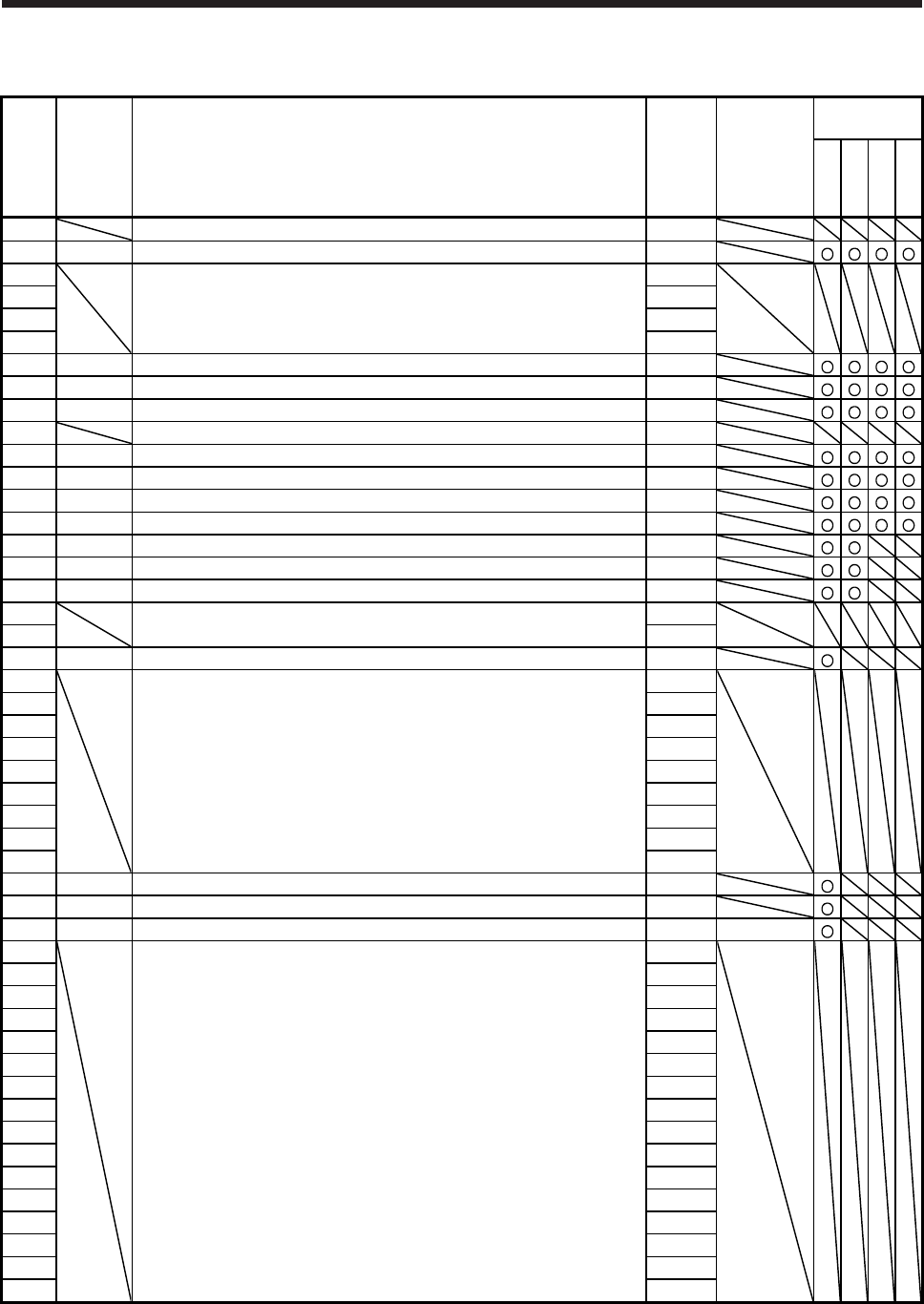
5.1.4 I/O setting parameters ([Pr. PD_ _ ])
No. Symbol Name
Initial
value
Unit
Operation
mode
Standard
Full.
Lin.
D.D.
PD01 For manufacturer setting 0000h
PD02 *DIA2 Input signal automatic on selection 2 0000h
PD03 For manufacturer setting 0020h
PD04 0021h
PD05 0022h
PD06 0000h
PD07 *DO1 Output device selection 1 0005h
PD08 *DO2 Output device selection 2 0004h
PD09 *DO3 Output device selection 3 0003h
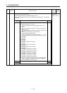
PD10 For manufacturer setting 0000h
PD11 *DIF Input filter setting (Note) 0004h
PD12 *DOP1 Function selection D-1 0000h
PD13 *DOP2 Function selection D-2 0000h
PD14 *DOP3 Function selection D-3 0000h
PD15 *IDCS Driver communication setting 0000h
PD16 *MD1 Driver communication setting - Master - Transmit data selection 1 0000h
PD17 *MD2 Driver communication setting - Master - Transmit data selection 2 0000h
PD18 For manufacturer setting 0000h
PD19 0000h
PD20 *SLA1 Driver communication setting - Slave - Master axis No. selection 1 0
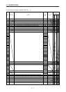
PD21 For manufacturer setting 0
PD22 0
PD23 0
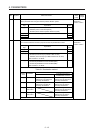
PD24 0000h
PD25 0000h
PD26 0000h
PD27 0000h
PD28 0000h
PD29 0000h
PD30 TLC Master-slave operation - Torque command coefficient on slave 0
PD31 VLC Master-slave operation - Speed limit coefficient on slave 0
PD32 VLL Master-slave operation - Speed limit adjusted value on slave 0 [r/min]
PD33 For manufacturer setting 0000h
PD34 0000h
PD35 0000h
PD36 0000h
PD37 0000h
PD38 0000h
PD39 0000h
PD40 0000h
PD41 0000h
PD42 0000h
PD43 0000h
PD44 0000h
PD45 0000h
PD46 0000h
PD47 0000h
PD48 0000h
Note. Refer to the servo system controller instruction manual for the setting.