


17. APPLICATION OF FUNCTIONS
17 - 62
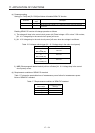
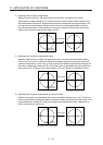
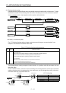
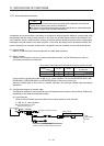
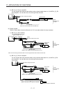
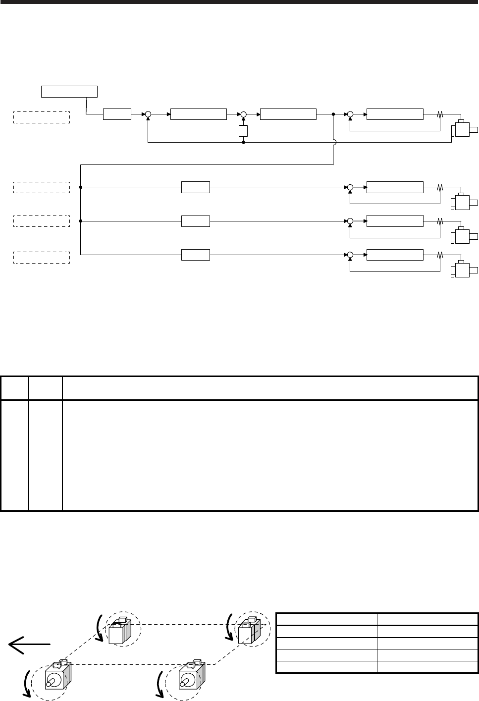
(4) Rotation direction setting
Rotation directions can be different among a controller command, master axis, and slave axes. To align
the directions, set [Pr. PA14] referring (4) of this section. Not doing so can cause such as an overload
due to a reverse direction torque against machine system rotation direction.
Controller
Master axis
Slave axis 1
Slave axis 2
Slave axis 3
Position control Speed control
S
Current control
+
--
Current control
Current control
Current control
[Pr. PA14]
0 or 1 (Note)
[Pr. PA14]
0 or 1 (Note)
[Pr. PA14]
0 or 1 (Note)
[Pr. PA14]
0 or 1 (Note)
+
-
+
-
+
-
+
-
+
POL
POL
POL
POL
Note. Setting "1" will reverse the polarity.
Fig. 17.1 Rotation direction setting of master and slave axes with torque command method for an
example of one master axis and three slave axes
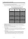
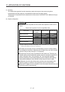
Table 17.1 Rotation direction setting parameter
No. Symbol Name and function
PA14 *POL Rotation direction selection
1. For master axis
Select a servo motor rotation direction of master axis to SSCNET controller command.
0: Servo motor CCW rotation in positioning address increase direction
1: Servo motor CW rotation in positioning address increase direction
2. For slave axis
Select servo motor rotation direction to a command from master axis.
0: Torque command polarity from master axis
1: Reverse of torque command polarity from master axis
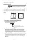
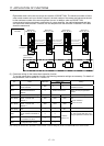
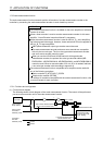
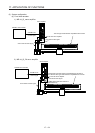
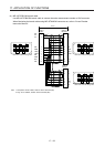
The following shows a setting example of rotation direction for a platform truck with one master axis and
three slave axes.
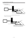
To set a rotation direction of the servo motor according to the moving direction, set the torque command
polarity to the slave axis 1 the same as that to the master axis, and set the opposite polarity to the slave
axis 2 and slave axis 3 from the master axis.
Slave axis 2
Slave axis 1Master axis
Slave axis 3
Moving direction
CW
CCW CCW
CW
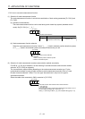
[Pr. PA14] setting
Axis [Pr. PA14]
Master axis 0
Slave axis 1 0
Slave axis 2 1
Slave axis 3 1