


14. USING A LINEAR SERVO MOTOR
14 - 30
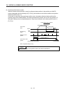
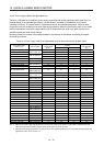
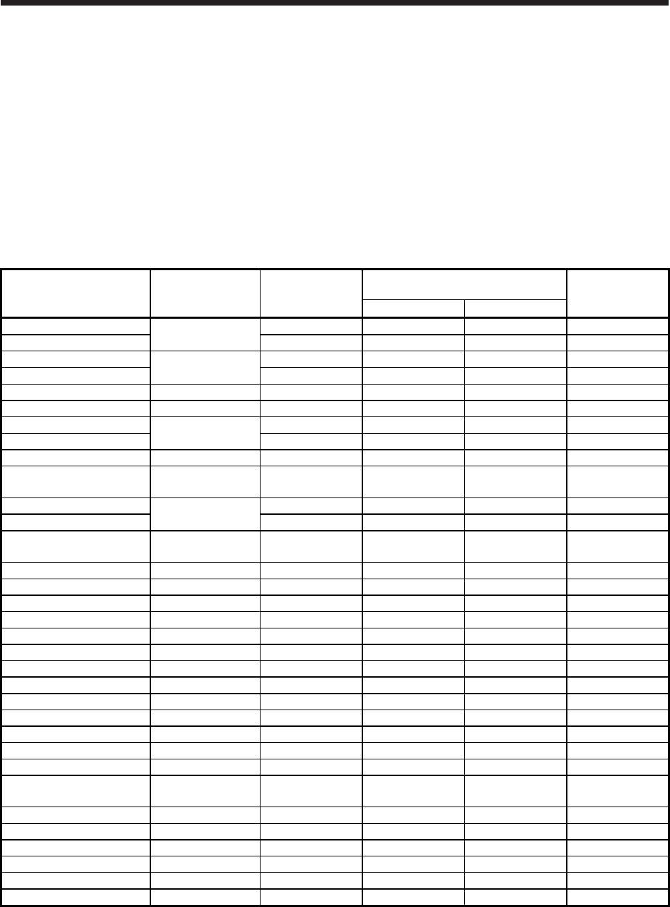
14.4.2 Power supply capacity and generated loss
Table 14.1 indicates servo amplifiers' power supply capacities and losses generated under rated load. For
thermal design of an enclosed type cabinet, use the values in the table in consideration for the worst
operating conditions. The actual amount of generated heat will be intermediate between values at rated
torque and servo-off according to the duty used during operation. When the linear servo motor is run at less
than the rated speed, the power supply capacity will be smaller than the value in the table, but the servo
amplifier's generated heat will not change.
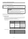
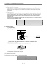
Mounting a heat sink outside of the cabinet enables to reduce heat in the cabinet and design a compact
enclosed type cabinet.
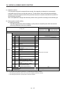
Table 14.1 Power supply capacity and generated loss per linear servo motor at rated output
Linear servo motor
(primary side)
Servo amplifier
Power supply
capacity [kVA]
(Note 1)
Servo amplifier-generated heat [W]
(Note 2)
Area required for
heat dissipation
[m
2
]
At rated output With servo-off
LM-H3P2A-07P-BSS0
MR-J4-40B(-RJ)
MR-J4-40B1(-RJ)
0.9 35 15 0.7
LM-H3P3A-12P-CSS0 0.9 35 15 0.7
LM-H3P3B-24P-CSS0
MR-J4-70B(-RJ)
1.3 50 15 1.0
LM-H3P3C-36P-CSS0 1.9 75 15 1.5
LM-H3P3D-48P-CSS0 MR-J4-200B(-RJ) 3.5 90 20 1.8
LM-H3P7A-24P-ASS0 MR-J4-70B(-RJ) 1.3 50 15 1.0
LM-H3P7B-48P-ASS0
MR-J4-200B(-RJ)
3.5 90 20 1.8
LM-H3P7C-72P-ASS0 3.8 100 20 1.1
LM-H3P7D-96P-ASS0 MR-J4-350B(-RJ) 5.5 130 20 2.7
LM-U2PAB-05M-0SS0
MR-J4-20B(-RJ)
MR-J4-20B1(-RJ)
0.5 25 15 0.5
LM-U2PAD-10M-0SS0
MR-J4-40B(-RJ)
MR-J4-40B1(-RJ)
0.9 35 15 0.7
LM-U2PAF-15M-0SS0 0.9 35 15 0.7
LM-U2PBB-07M-1SS0
MR-J4-20B(-RJ)
MR-J4-20B1(-RJ)
0.5 25 15 0.5
LM-U2PBD-15M-1SS0 MR-J4-60B(-RJ) 1.0 40 15 0.8
LM-U2PBF-22M-1SS0 MR-J4-70B(-RJ) 1.3 50 15 1.0
LM-U2P2B-40M-2SS0 MR-J4-200B(-RJ) 3.5 90 20 1.8
LM-U2P2C-60M-2SS0 MR-J4-350B(-RJ) 5.5 130 20 2.7
LM-U2P2D-80M-2SS0 MR-J4-500B(-RJ) 7.5 195 25 3.9
LM-FP2B-06M-1SS0 MR-J4-200B(-RJ) 3.5 90 20 1.8
LM-FP2D-12M-1SS0 MR-J4-500B(-RJ) 7.5 195 25 3.9
LM-FP2F-18M-1SS0 MR-J4-700B(-RJ) 10 300 25 6.0
LM-FP4B-12M-1SS0 MR-J4-500B(-RJ) 7.5 195 25 3.9
LM-FP4D-24M-1SS0 MR-J4-700B(-RJ) 10 300 25 6.0
LM-FP4F-36M-1SS0 MR-J4-11KB(-RJ) 14 460 45 9.2
LM-FP4H-48M-1SS0 MR-J4-15KB(-RJ) 18 580 45 11.6
LM-FP5H-60M-1SS0 MR-J4-22KB4(-RJ) 22 640 45 12.8
LM-K2P1A-01M-2SS1
MR-J4-40B(-RJ)
MR-J4-40B1(-RJ)
0.9 35 15 0.7
LM-K2P1C-03M-2SS1 MR-J4-200B(-RJ) 3.5 90 20 1.8
LM-K2P2A-02M-1SS1 MR-J4-70B(-RJ) 1.3 50 15 1.0
LM-K2P2C-07M-1SS1 MR-J4-350B(-RJ) 5.5 130 20 2.7
LM-K2P2E-12M-1SS1 MR-J4-500B(-RJ) 7.5 195 25 3.9
LM-K2P3C-14M-1SS1 MR-J4-350B(-RJ) 5.5 130 20 2.7
LM-K2P3E-24M-1SS1 MR-J4-500B(-RJ) 7.5 195 25 3.9
Note 1. Note that the power supply capacity will vary according to the power supply impedance. This value is applicable when the
power factor improving AC reactor or power factor improving DC reactor are not used.
2. Heat generated during regeneration is not included in the servo amplifier-generated heat. To calculate heat generated by the
regenerative option, refer to section 11.2.