


1. FUNCTIONS AND CONFIGURATION
1 - 18
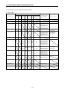
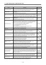
Note 1. 0.3 A is the value applicable when all I/O signals are used. The current capacity can be decreased by reducing the number of
I/O points.
2. When closely mounting the servo amplifier of 3.5 kW or less, operate them at the ambient temperatures of 0 ˚C to 45 ˚C or at
75% or smaller effective load ratio.
3. Test pulse is a signal which instantaneously turns off a signal to the servo amplifier at a constant period for external circuit to
self-diagnose.
4. MR-J4-_B servo amplifier is compatible only with two-wire type. MR-J4-_B-RJ servo amplifier is compatible with two-wire type,
four-wire type, and A/B/Z-phase differential output method. Refer to table 1.1 for details.
5. For the compatible version of fully closed loop system, refer to table 1.1. Check the software version of the servo amplifier
using MR Configurator2.
6 The communication cycle depends on the controller specifications and the number of axes connected.
7. For the compatible version for the scale measurement function, refer to table 1.1. Check the software version of the servo
amplifier using MR Configurator2.