APPENDIX
App. - 23
App. 5.7.3 When using MR-J3-D05 with an MR-J4 series servo amplifier
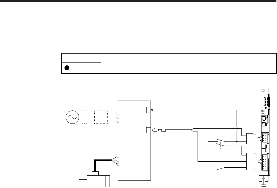
(1) System configuration diagram
The following shows the connection targets of the STO switch and STO release switch.
POINT
MR-D05UDL_M (STO cable) for MR-J3 series cannot be used.
MR-J3-D05
FG
STO switch
STO release switch
Magnetic
contactor
MCCB
Power
supply
Servo motor
MR-J4_B_(-RJ)
STO cable
MR-D05UDL3M-B
CN9
CN10
CN8
CN3
L1
L2
L3
U
V
W
EM2 (Forced stop 2)


