11. OPTIONS AND PERIPHERAL EQUIPMENT
11 - 78
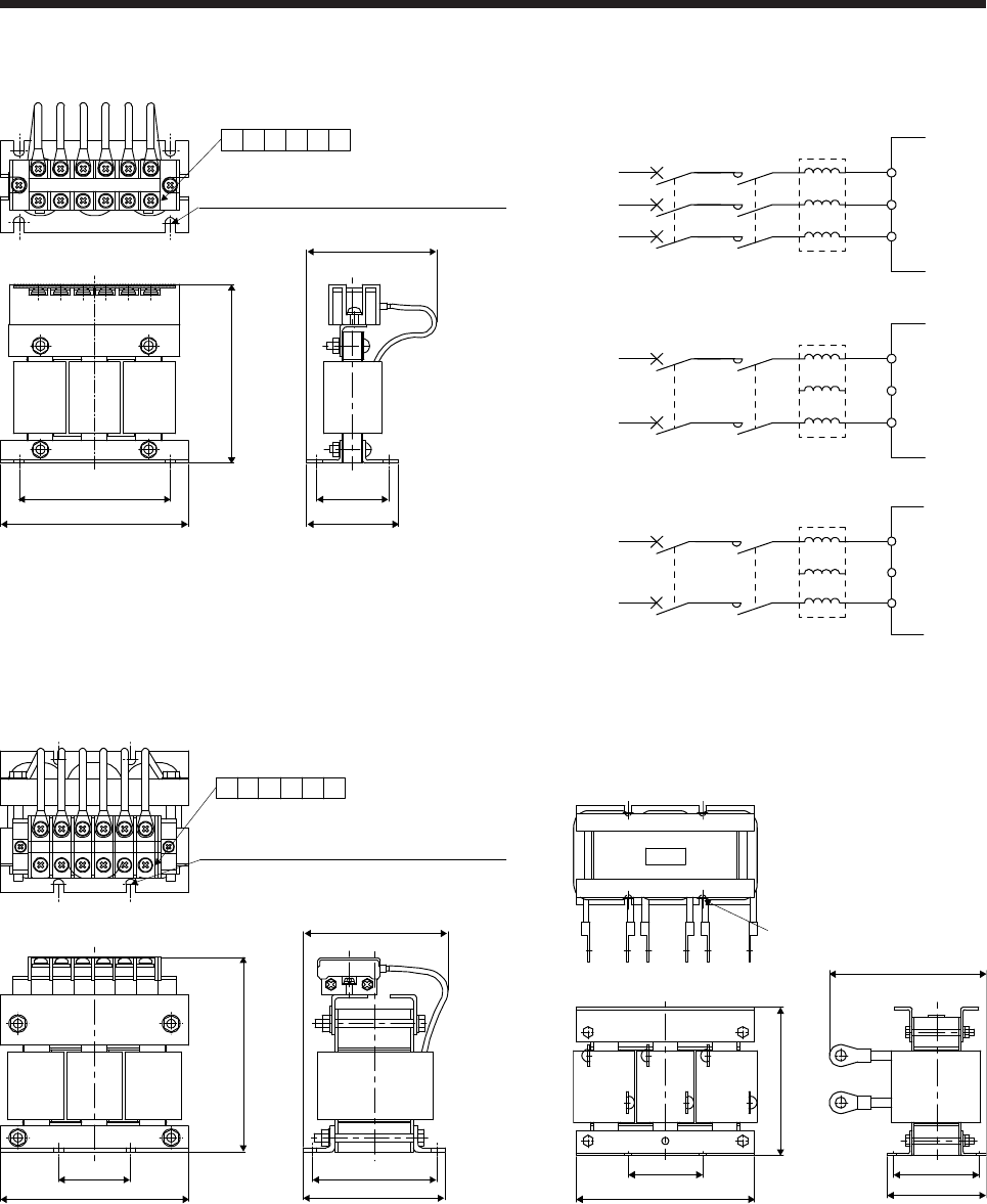
(1) 200 V class/100 V class
4-d mounting hole
(Varnish is removed from front right mounting
hole (face and back side).) (Note 1)
Terminal layout
RX ZSYT
W or less (Note 2)
W1
D1
D2
H
D or less
Fig. 11.7
Y
Z
S
T
Y
Z
S
T
MCMCCB
MCMCCB
FR-HAL
Servo amplifier
3-phase 200 V class
XR
L1
L2
L3
3-phase
200 V AC to
240 V AC
FR-HAL
Servo amplifier
1-phase 200 V class
XR
L1
L2
(Note)
1-phase
200 V AC to
240 V AC
L3
Y
Z
S
T
MCMCCB
FR-HAL
Servo amplifier
1-phase 100 V class
XR
L1
1-phase
100 V AC to
120 V AC
L2
Unassigned
Note 1. Use this for grounding. Note. For 1-phase 200 V AC to 240 V AC, connect the power
supply to L1 and L3. Leave L2 open. 2. W ± 2 is applicable for FR-HAL-0.4K to FR-HAL-1.5K.
4-d mounting hole
(Varnish is removed from front right mounting
hole (face and back side).) (Note)
Terminal layout
RX ZSYT
W ± 2
H
D1
D or less
W1
D2
Fig. 11.8
X
D or less
D1 ± 2
D2
W1
W or less
R
T
S
Y
Z
H ± 5
4-d mounting hole (Note)
Fig. 11.9
Note. Use this for grounding. Note. Use this for grounding.


