


3. SIGNALS AND WIRING
3 - 33
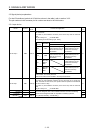
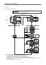
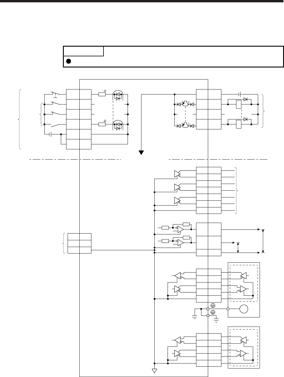
3.8 Interfaces
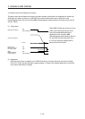
3.8.1 Internal connection diagram
POINT
Refer to section 13.3.1 for the CN8 connector.
3
CN3
6
16
7
17
8
18
LA
LAR
LB
LBR
LZ
LZR
2
4
7
8
MR
MRR
MX
MXR
LG
PE
M
CN2
CN3
MO1
MO2
LG
4
14
1
LG11
EM2
CN3
20
DI1 2
DI2 12
DI3 19
DICOM
5
10
CN3
3
13
9
15
DOCOM
INP
ALM
USB
D+
GND
D- 2
3
5
CN5
MBR
DICOM
RA
RA
3
2
4
7
8
MR2
MRR2
MX2
MXR2
LG
External encoder
(Note 4, 6) CN2L
±10 V DC
±10 V DC
Encoder
Differential line
driver output
(35 mA or less)
Servo motor
Analog monitor
(Note 2)
Servo amplifie
r
(Note 1)
24 V DC
Forced stop 2
(Note 3)
(Note 3)
Isolated
Approximately
6.2 k
Approximately
6.2 k
Encoder
(Note 5)
24 V DC
(Note 5)
Note 1. Signal can be assigned for these pins with the controller setting.
For contents of signals, refer to the instruction manual of the controller.
2. The signal cannot be used in the speed control mode and torque control mode.
3. This diagram is for sink I/O interface. For source I/O interface, refer to section 3.8.3.
4. This is for MR-J4-_B_-RJ servo amplifier. MR-J4-_B_ servo amplifier does not have CN2L connector.
5. The illustration of the 24 V DC power supply is divided between input signal and output signal for convenience. However, they
can be configured by one.
6. Refer to table 1.1 for connections of external encoders.