


8. TROUBLESHOOTING
8 - 8
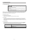
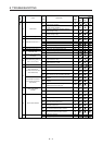
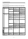
8.4 Troubleshooting at power on
When the servo system does not boot and system error occurs at power on of the servo system controller,
improper boot of the servo amplifier might be the cause. Check the display of the servo amplifier, and take
actions according to this section.
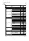
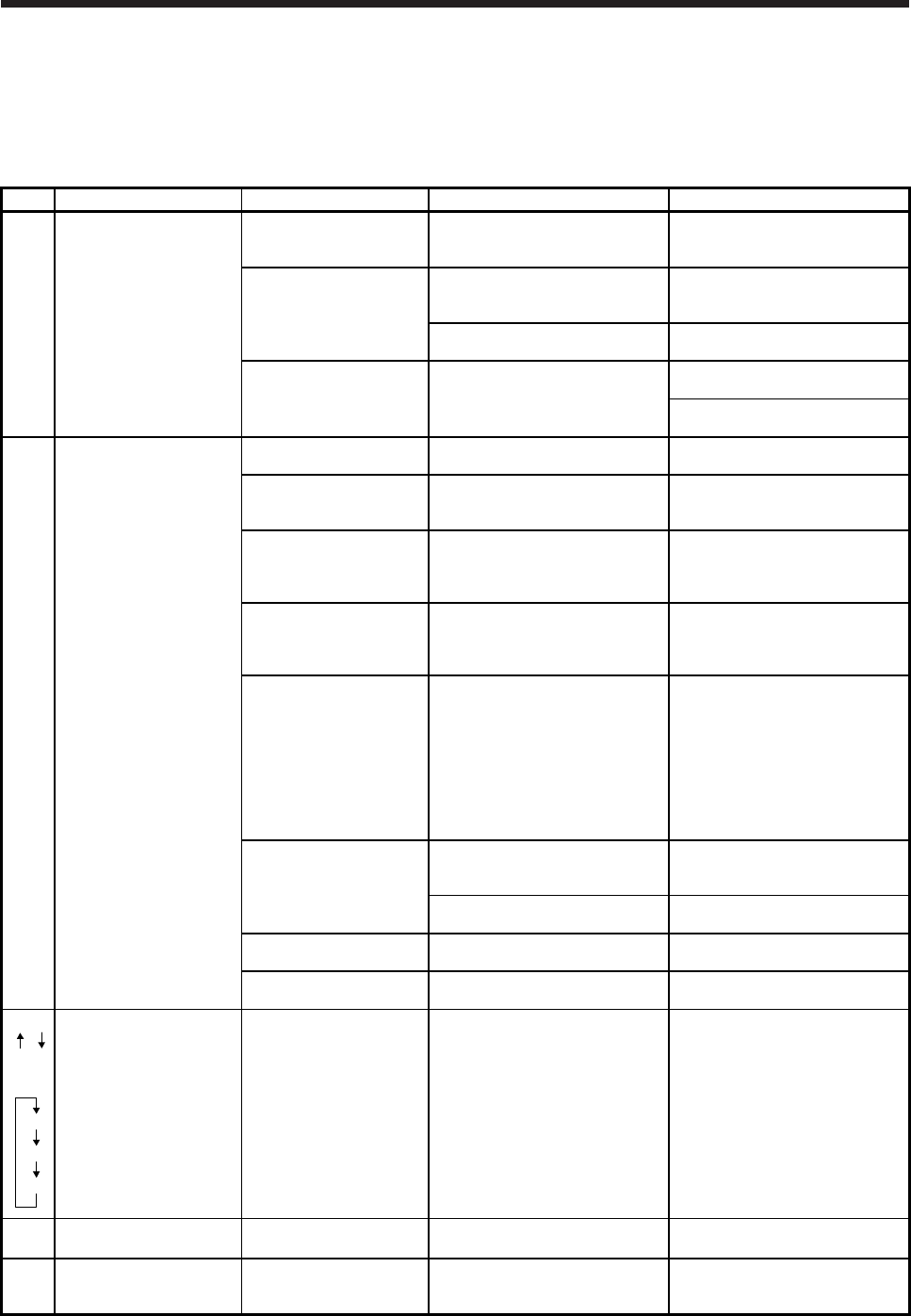
Display Description Cause Checkpoint Action
AA Communication with the
servo system controller
has disconnected.
The power of the servo
system controller was
turned off.
Check the power of the servo
system controller.
Switch on the power of the servo
system controller.
A SSCNET III cable was
disconnected.
"AA" is displayed in the
corresponding axis and following
axes.
Replace the SSCNET III cable of
the corresponding axis.
Check if the connectors (CNIA,
CNIB) are unplugged.
Connect it correctly.
The power of the servo
amplifier was turned off.
"AA" is displayed in the
corresponding axis and following
axes.
Check the power of the servo
amplifier.
Replace the servo amplifier of the
corresponding axis.
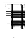
Ab Initialization
communication with the
servo system controller
has not completed.
The control axis is
disabled.
Check if the disabling control axis
switch (SW2-2) is on.
Turn off the disabling control axis
switch (SW2-2).
The setting of the axis
No. is incorrect.
Check that the other servo
amplifier is not assigned to the
same axis No.
Set it correctly.
Axis No. does not match
with the axis No. set to
the servo system
controller.
Check the setting and axis No. of
the servo system controller.
Set it correctly.
Information about the
servo series has not set
in the simple motion
module.
Check the value set in Servo
series (Pr.100) in the simple
motion module.
Set it correctly.
Communication cycle
does not match.
Check the communication cycle
at the servo system controller
side.
When using 8 axes or less: 0.222
ms
When using 16 axes or less:
0.444 ms
When using 32 axes or less:
0.888 ms
Set it correctly.
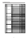
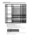
A SSCNET III cable was
disconnected.
"Ab" is displayed in the
corresponding axis and following
axes.
Replace the SSCNET III cable of
the corresponding axis.
Check if the connectors (CNIA,
CNIB) are unplugged.
Connect it correctly.
The power of the servo
amplifier was turned off.
"Ab" is displayed in an axis and
the following axes.
Check the power of the servo
amplifier.
The servo amplifier is
malfunctioning.
"Ab" is displayed in an axis and
the following axes.
Replace the servo amplifier of the
corresponding axis.
Ab
AC
or
Ab
AC
Ad
Communication between
servo system controller
and servo amplifier are
repeating connection and
shut-off.
An MR-J4-_B_(-RJ) servo
amplifier or MR-J4W_-_B
servo amplifier which is
set to J3 compatibility
mode is connected to the
SSCNET III/H network.
Check if "J3 compatibility mode"
is set using "MR-J4(W)-B mode
selection" which came with MR
Configurator2.
Select "J4 mode" with "MR-
J4(W)-B mode selection".
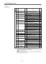
b##.
(Note)
The system has been in
the test operation mode.
Test operation mode has
been enabled.
Test operation setting switch
(SW2-1) is turned on.
Turn off the test operation setting
switch (SW2-1).
off Operation mode for
manufacturer setting is
set.
Operation mode for
manufacturer setting is
enabled.
Check if all of the control axis
setting switches (SW2) are on.
Set the control axis setting
switches (SW2) correctly.
Note. ## indicates axis No.