


1. FUNCTIONS AND CONFIGURATION
1 - 46
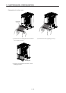
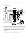
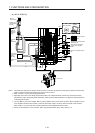
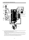
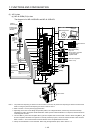
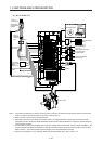
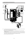
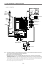
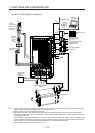
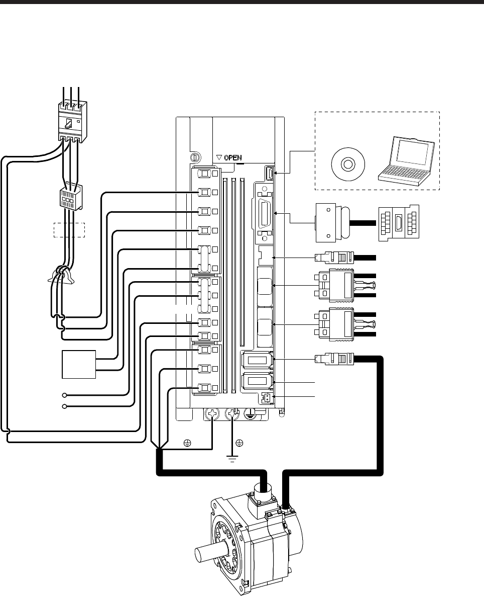
(2) 400 V class
(a) MR-J4-200B4(-RJ) or less
The diagram is for MR-J4-60B4-RJ and MR-J4-100B4-RJ.
CN4
CN5
P+
C
L11
L21
P3
P4
MR Configurator2
CN3
CN8
CN1A
CN1B
CN2
CN2L (Note 4)
W
V
U
L1
L2
L3
(Note 1)
Junction terminal
block
To safety relay or
MR-J3-D05 safety
logic unit
Servo system controller
or previous servo
amplifier CN1B
Next servo amplifier
CN1A or cap
RST
Molded-case
circuit breaker
(MCCB)
(Note 2)
Power supply
(Note 3)
Magnetic
contactor
(MC)
Line noise filter
(FR-BSF01)
Regenerative
option
Power factor
improving DC
reactor
(FR-HEL-H)
Servo motor
Personal
computer
Battery
D (Note 5)
Note 1. The power factor improving AC reactor can also be used. In this case, the power factor improving DC reactor cannot be used.
When not using the power factor improving DC reactor, short P3 and P4.
2. Refer to section 1.3 for the power supply specification.
3. Depending on the main circuit voltage and operation pattern, bus voltage decreases, and that may cause the forced stop
deceleration to shift to the dynamic brake deceleration. When dynamic brake deceleration is not required, slow the time to turn
off the magnetic contactor.
4. This is for MR-J4-_B4-RJ servo amplifier. MR-J4-_B4 servo amplifier does not have CN2L connector. When using MR-J4-_B4-
RJ servo amplifier in the linear servo system or in the fully closed loop system, connect an external encoder to this connector.
Refer to Table 1.1 and "Linear Encoder Instruction Manual" for the compatible external encoders.
5.
A
lways connect between P+ and D terminals. When using the regenerative option, refer to section 11.2.