


1. FUNCTIONS AND CONFIGURATION
1 - 26
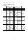
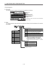
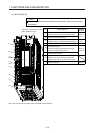
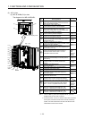
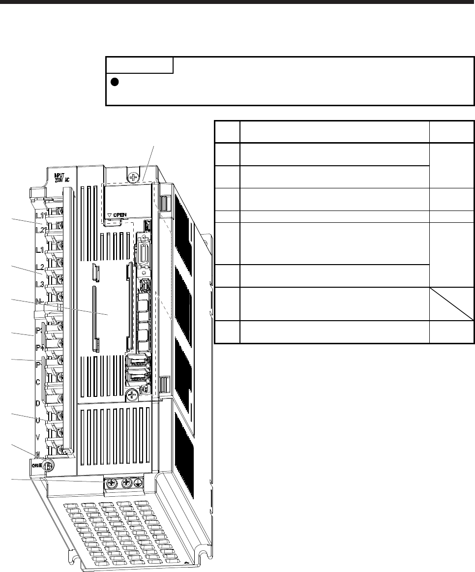
(c) MR-J4-500B(-RJ)
POINT
The servo amplifier is shown with the front cover open. The front cover cannot
be removed.
(1)
(3)
(2)
(Note)
(8)
(4)
Side
(5)
(6)
(7)
The broken line area is the same as
MR-J4-200B(-RJ) or less.
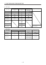
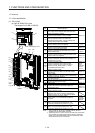
No. Name/Application
Detailed
explanation
(1)
Control circuit terminal block (TE2)
Used to connect the control circuit power supply.
Section 3.1
Section 3.3
(2)
Main circuit terminal block (TE1)
Connect the input power supply.
(3)
Battery holder
Install the battery for absolute position data backup.
Section
12.2
(4) Rating plate Section 1.6
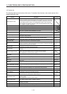
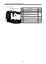
(5)
Regenerative option/power factor improving reactor
terminal block (TE3)
Used to a connect a regenerative option and a
power factor improving DC reactor.
Section 3.1
Section 3.3
(6)
Servo motor power supply terminal block (TE4)
Connect the servo motor.
(7)
Charge lamp
When the main circuit is charged, this will light.
While this lamp is lit, do not reconnect the cables.
(8)
Protective earth (PE) terminal
Grounding terminal
Section 3.1
Section 3.3
Note. Lines for slots around the battery holder are omitted from the illustration.