


13. USING STO FUNCTION
13 - 10
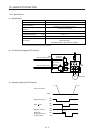
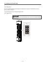
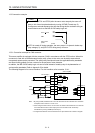
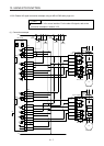
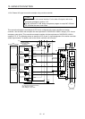
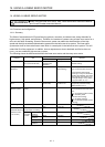
13.3.4 External I/O signal connection example using a motion controller
POINT
This connection is for source interface. For the other I/O signals, refer to the
connection examples in section 3.2.2.
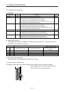
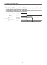
For MC-Y0B and PC-Y0B, design a sequence program to output MC-Y0B and
PC-Y0B after the servo motor stops.
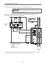
This connection diagram is an example of STO circuit configured with a servo amplifier and motion
controller. Use the switch that complies with the requirement of ISO/EN ISO 13849-1 category 3 PL d as an
emergency stop switch. This connection example complies with the requirement of ISO/EN ISO 13849-1
category 3 PL d. The following shows an example of I/O (X and Y) signal assignment of the motion controller
safety signal module. For details, refer to the motion controller user’s manual.
Shut-off
signal (MC)
Shut-off verification
signal (M)
Shut-off verification
signal (PLC)
Shut-off
signal (PLC)
Door signal (PLC)
24 V
0 V
Control circuit
Servo amplifier
STOCOM
STO2
Servo motor
S1: STO shut-off switch (STO switch)
KM1: Magnetic contactor
EMG: Emergency stop switch
Door signal (MC)
Q17_DSCPU
0 V
24 V DC
0 V
24 V DC
Programmable
controller CPU
(iQ platform
compatible)
Motion controller
safety signal module
(Q173DSXY)
CPU
(iQ platform compatible)
S1
CN8
KM1
CN3
EM2KM1
STO1
TOFB1
TOFCOM
TOFB2
EM2
EMG
M
B09
B1
B19
B20
B09
B1
B19
B20
A1
A1
PC-X00
PC-X01
PLC I/O
MC-X01
MC-Y0B
MC-X00
MC I/O
PC-Y0B