


4. STARTUP
4 - 13
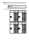
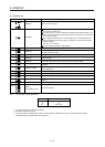
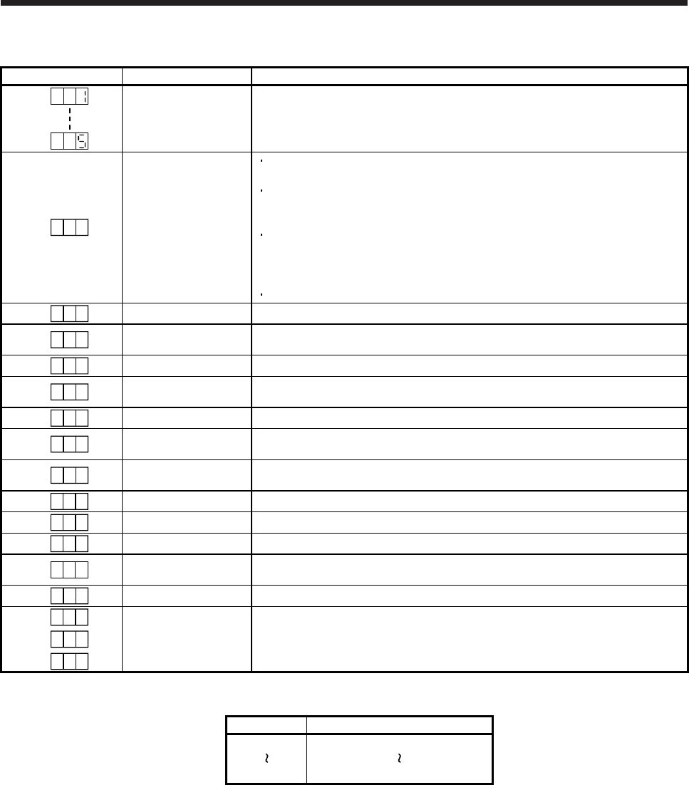
(2) Indication list
Indication Status Description
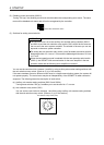
Initializing System check in progress
A b
Initializing
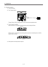
Power of the servo amplifier was switched on at the condition that the power of the
servo system controller is off.
The control axis No. set to the auxiliary axis number setting switches (SW2-3 and
SW2-4) and the axis selection rotary switch (SW1) do not match the one set to the
servo system controller.
A servo amplifier malfunctioned, or communication error occured with the servo
system controller or the previous axis servo amplifier. In this case, the indication
changes as follows:
"Ab", "AC", "Ad", and "Ab"
The servo system controller is malfunctioning.
A b .
Initializing During initial setting for communication specifications
A C
Initializing
Initial setting for communication specifications completed, and then it synchronized
with servo system controller.
A d
Initializing During initial parameter setting communication with servo system controller
A E
Initializing
During the servo motor/encoder information and telecommunication with servo
system controller
A F
Initializing During initial signal data communication with servo system controller
A H
Initializing completion
The process for initial data communication with the servo system controller is
completed.
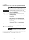
A A
Initializing standby
The power supply of servo system controller is turned off during the power supply of
servo amplifier is on.
(Note 1)
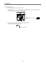
b # #
Ready-off The ready-off signal from the servo system controller was received.
(Note 1)
d # #
Servo-on The ready-off signal from the servo system controller was received.
(Note 1)
C # #
Servo-off The ready-off signal from the servo system controller was received.
(Note 2)
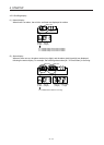
* **
Alarm and warning
The alarm No. and the warning No. that occurred is displayed. (Refer to section 8.
(Note 4))
8 88
CPU error CPU watchdog error has occurred.
(Note 1)
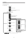
# #b.
(Note 3)
Test operation mode
Motor-less operation
# #d.
# #C.
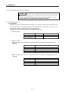
Note 1. The meanings of ## are listed below.
## Description
01 Axis No. 1
64 Axis No. 64
2. ** indicates the alarm No. and the warning No.
3. Requires the MR Configurator2.
4. Only a list of alarms and warnings is listed in chapter 8. Refer to "MELSERVO-J4 Servo Amplifier Instruction Manual
(Troubleshooting)" for details of alarms and warnings.