


11. OPTIONS AND PERIPHERAL EQUIPMENT
11 - 77
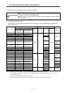
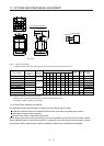
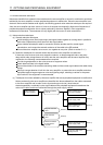
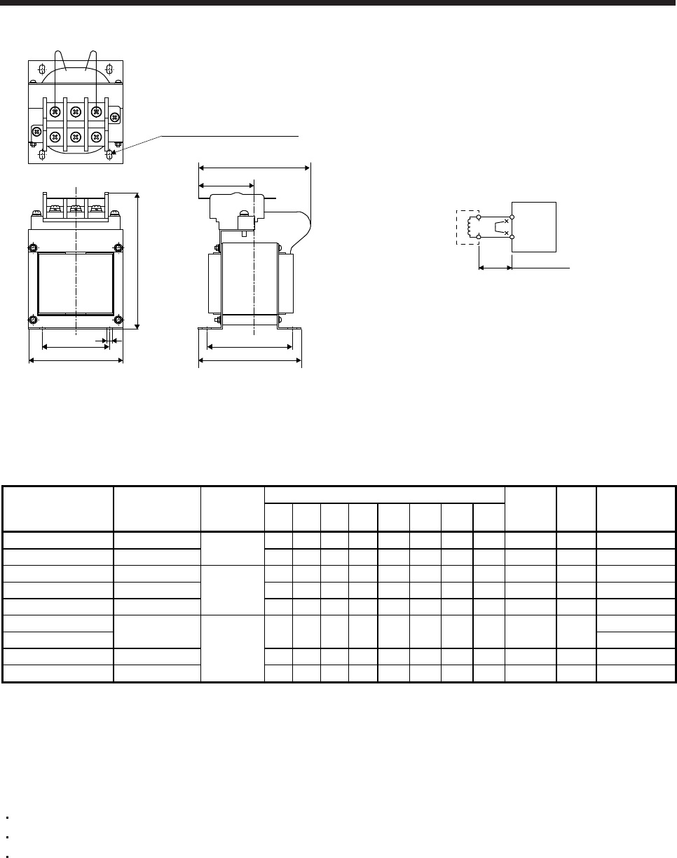
H ± 2.5
W1
W ± 2.5
D2
D1 ± 1
PP1
D or less
(D3)
4-d mounting hole (Note 1)
6
Fig. 11.6
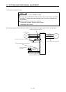
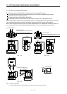
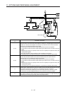
(Note 2)
Servo amplifie
r
P3
P4
FR-HEL-H
5 m or less
Note 1. Use this for grounding.
2. When using the power factor improving DC reactor, remove the short bar across P3 and P4.
Servo amplifier
Power factor
improving DC
reactor
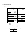
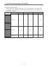
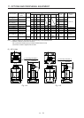
Dimensions
Dimensions [mm]
Terminal
size
Mass
[kg]
Wire [mm
2
]
(Note)
W W1 H D D1 D2 D3 d
MR-J4-60B4(-RJ) FR-HEL-H1.5K
Fig. 11.4
66 50 100 80 74 54 37 M4 M3.5 1.0 2 (AWG 14)
MR-J4-100B4(-RJ) FR-HEL-H2.2K 76 50 110 80 74 54 37 M4 M3.5 1.3 2 (AWG 14)
MR-J4-200B4(-RJ) FR-HEL-H3.7K 86 55 120 95 89 69 45 M4 M4 2.3 2 (AWG 14)
MR-J4-350B4(-RJ) FR-HEL-H7.5K Fig. 11.5 96 60 128 105 100 80 50 M5 M4 3.5 2 (AWG 14)
MR-J4-500B4(-RJ) FR-HEL-H11K 105 75 137 110 105 85 53 M5 M5 4.5 3.5 (AWG 12)
MR-J4-700B4(-RJ)
FR-HEL-H15K
Fig. 11.6
105 75 152 125 115 95 62 M5 M6 5.0
5.5 (AWG 10)
MR-J4-11KB4(-RJ) 8 (AWG 8)
MR-J4-15KB4(-RJ) FR-HEL-H22K 133 90 178 120 95 75 53 M5 M6 6.0 8 (AWG 8)
MR-J4-22KB4(-RJ) FR-HEL-H30K 133 90 178 120 100 80 56 M5 M6 6.5 14 (AWG 6)
Note. Selection conditions of wire size is as follows.
Wire type: 600 V grade heat-resistant polyvinyl chloride insulated wire (HIV wire)
Construction condition: Single wire set in midair
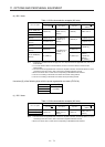
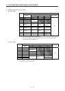
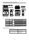
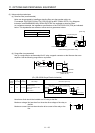
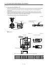
11.12 Power factor improving AC reactors
The following shows the advantages of using power factor improving AC reactor.
It improves the power factor by increasing the form factor of the servo amplifier's input current.
It decreases the power supply capacity.
The input power factor is improved to about 80%.
When using power factor improving reactors for two servo amplifiers or more, be sure to connect a power
factor improving reactor to each servo amplifier. If using only one power factor improving reactor, enough
improvement effect of phase factor cannot be obtained unless all servo amplifiers are operated.