


APPENDIX
App. - 45
Note 1. Encoder pulse unit.
2.
A
vailable in position control mode
3. This cannot be used in the torque control mode.
4. This can be used with MR Configurator2 with software version 1.19V or later.
5. This cannot be used in the speed control mode.
6. Output in the load-side encoder unit for the fully closed loop control. Output in the servo motor encoder unit for the semi closed
loop control.
7. For 400 V class servo amplifier, the bus voltage becomes +8 V/800 V.
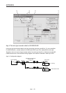
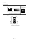
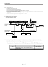
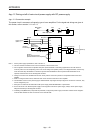
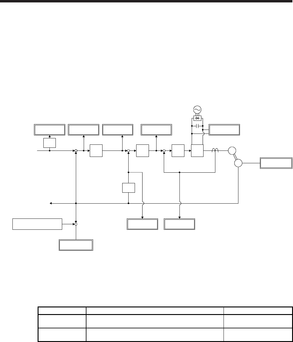
(3) Analog monitor block diagram
(a) Semi closed loop control
Droop pulses
Speed
command
Position
control
Speed
control
PWM
Current
control
Current
command
Bus voltage
Speed
command
Current
encoder
+
Servo motor
Encoder
Current feedback
Position feedback
M
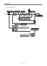
Position command
received from a
servo system
controller
Position feedback data
returned to a servo
system controller
Differen-
tiation
Differen-
tiation
Feedback position
standard position(Note)
Feedback
position
+
-
Encoder inside
temperature
Servo motor
speed
Torque
+
+
-
-
+
-
Speed
command 2
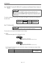
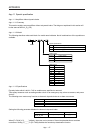
Note. The feedback position is output based on the position data passed between servo system controller and servo amplifier. [Pr.
PC13] and [Pr. PC14] can set up the standard position of feedback position that is output to analog monitor in order to adjust the
output range of feedback position. The setting range is between -9999 pulses and 9999 pulses.
Standard position of feedback position = [Pr. PC14] setting value × 10000 + [Pr. PC13] setting value
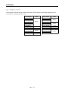
Parameter Description Setting range
PC13
Sets the lower-order four digits of the standard position of
feedback position
-9999 to 9999 [pulse]
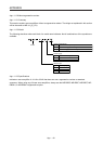
PC14
Sets the higher-order four digits of the standard position of
feedback position
-9999 to 9999 [10000 pulses]