


1. FUNCTIONS AND CONFIGURATION
1 - 36
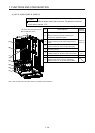
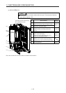
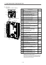
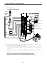
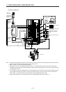
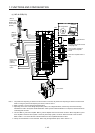
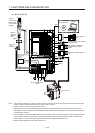
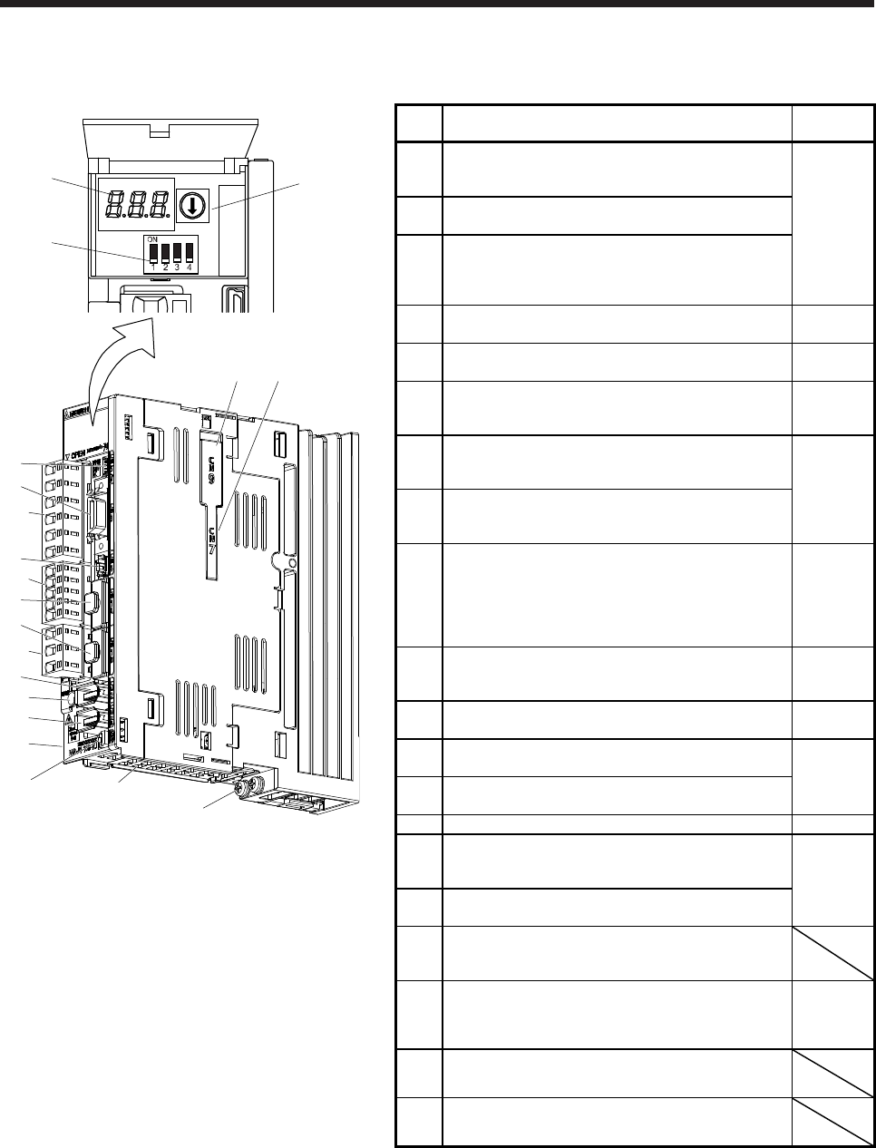
(3) 100 V class
The diagram is for MR-J4-10B1-RJ.
(1)
(3)
(2)
Inside of the display cover
(5)
(18)
(13)
(10)
(17)
(9)
(6)
(7)
(11)
Bottom
(16)
(15)
(8)
(4)
(14)
Side
(12)
(19)(20)
No. Name/Application
Detailed
explanation
(1)
Display
The 3-digit, seven-segment LED shows the servo
status and the alarm number.
Section 4.3
(2)
Axis selection rotary switch (SW1)
Used to set the axis No. of servo amplifier.
(3)
Control axis setting switch (SW2)
The test operation switch, the control axis
deactivation setting switch, and the auxiliary axis
number setting switch are available.
(4)
USB communication connector (CN5)
Connect with the personal computer.
Section
11.7
(5)
I/O signal connector (CN3)
Used to connect digital I/O signals.
Section 3.2
Section 3.4
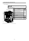
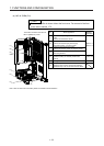
(6)
STO input signal connector (CN8)
Used to connect MR-J3-D05 safety logic unit and
external safety relay.
Chapter 13
App. 5
(7)
SSCNET III cable connector (CN1A)
Used to connect the servo system controller or the
previous axis servo amplifier.
Section 3.2
Section 3.4
(8)
SSCNET III cable connector (CN1B)
Used to connect the next axis servo amplifier. For
the final axis, put a cap.
(9)
(Note
2)
Encoder connector (CN2)
Used to connect the servo motor encoder.
Used to connect the servo motor encoder or
external encoder. Refer to table 1.1 for the
compatible external encoders.
Section 3.4
"Servo
Motor
Instruction
Manual
(Vol. 3)"
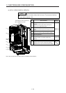
(10)
Battery connector (CN4)
Used to connect the battery for absolute position
data backup.
Chapter 12
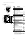
(11)
Battery holder
Install the battery for absolute position data backup.
Section
12.2
(12)
Protective earth (PE) terminal
Grounding terminal
Section 3.1
Section 3.3
(13)
Main circuit power supply connector (CNP1)
Connect the input power supply.
(14) Rating plate Section 1.6
(15)
Control circuit power supply connector (CNP2)
Connect the control circuit power supply and
regenerative option.
Section 3.1
Section 3.3
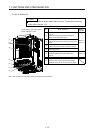
(16)
Servo motor power output connector (CNP3)
Connect the servo motor.
(17)
Charge lamp
When the main circuit is charged, this will light.
While this lamp is lit, do not reconnect the cables.
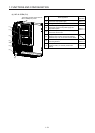
(18)
(Note
1, 2)
External encoder connector (CN2L)
Refer to table 1.1 for connections of external
encoders.
"Linear
Encoder
Instruction
Manual"
(19)
Optional unit connector 1 (CN7)
This is for connecting the optional unit. This
connector is attached only on MR-J4-_B_-RJ.
(20)
Optional unit connector 2 (CN9)
This is for connecting the optional unit. This
connector is attached only on MR-J4-_B_-RJ.
Note 1. This is for MR-J4-_B1-RJ servo amplifier. MR-J4-_B1 servo
amplifier does not have CN2L connector.
2. "External encoder" is a term for linear encoder used in the linear
servo system, load-side encoder used in the fully closed loop
system, and scale measurement encoder used with the scale
measurement function in this manual.