


13. USING STO FUNCTION
13 - 13
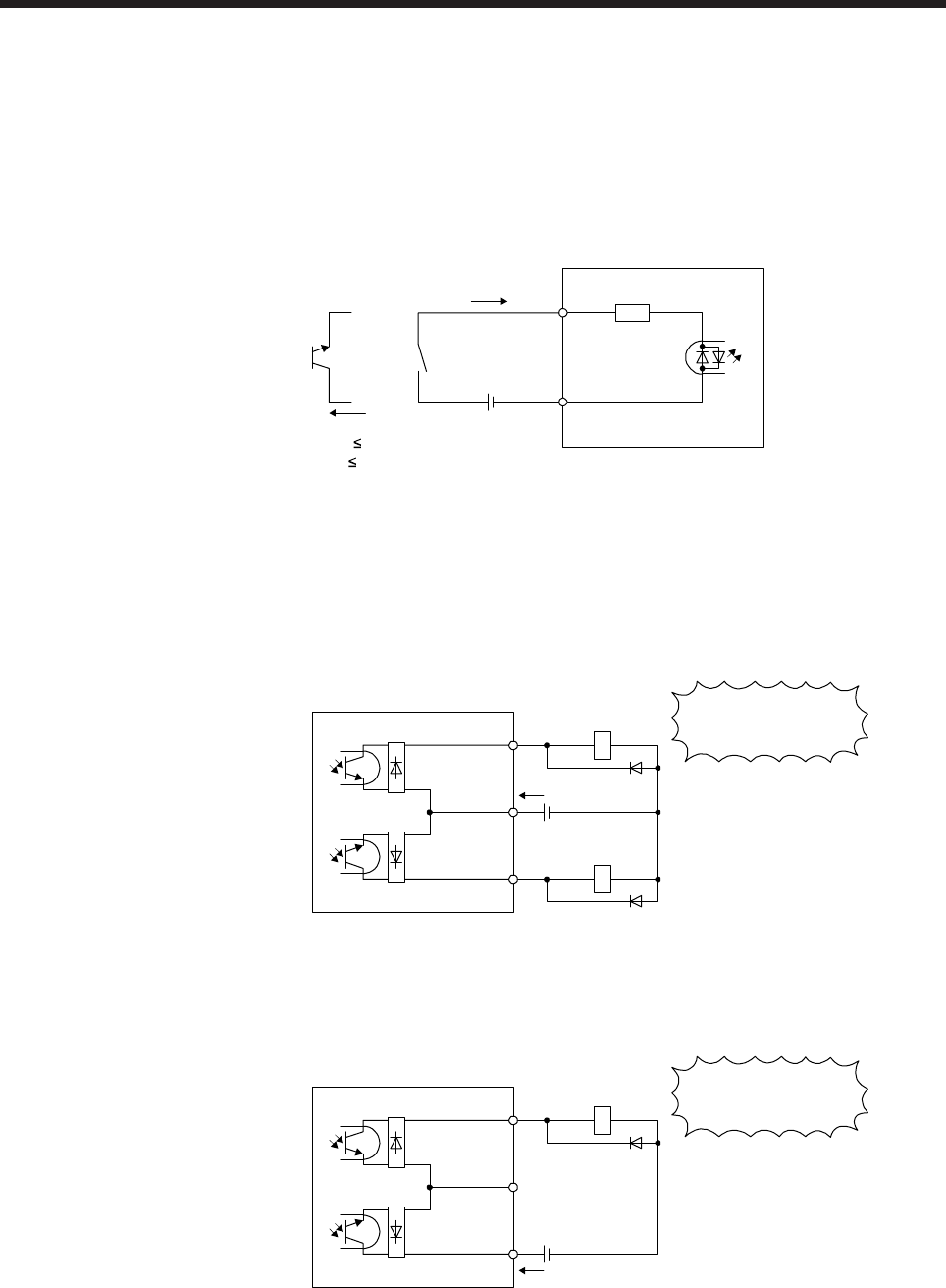
13.4.2 Source I/O interface
In this servo amplifier, source type I/O interfaces can be used.
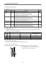
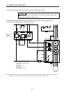
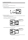
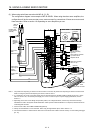
(1) Digital input interface DI-1
This is an input circuit whose photocoupler anode side is input terminal. Transmit signals from source
(open-collector) type transistor output, relay switch, etc.
Approx. 3.0 kΩ
STO1
STO2
Servo amplifie
r
Switch
STOCOM
TR
Approx. 5 mA
V
CES
1.0 V
I
CEO
100 µA
24 V DC ± 10%
300 mA
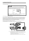
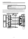
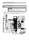
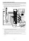
(2) Digital output interface DO-1
This is a circuit of emitter output terminal of the output transistor. When the output transistor is turned on,
current will be applied from the output to a load.
A maximum of 5.2 V voltage drop occurs in the servo amplifier.
(a) When outputting two STO states by using each TOFB
Servo amplifier
Load
(Note)
24 V DC ± 10%
300 mA
TOFCOM
TOFB2
TOFB1
Load
If polarity of diode is
reversed, servo amplifier
will malfunction.
Note. If the voltage drop (maximum of 2.6 V) interferes with the relay operation, apply high
voltage (maximum of 26.4 V) from external source.
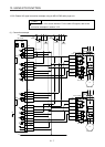
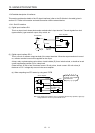
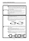
(b) When outputting two STO states by using one TOFB
Servo amplifier
Load
(Note)
24 V DC ± 10%
300 mA
TOFCOM
TOFB2
TOFB1
If polarity of diode is
reversed, servo amplifier
will malfunction.
Note. If the voltage drop (maximum of 5.2 V) interferes with the relay operation, apply high
voltage (maximum of 26.4 V) from external source.