


3. SIGNALS AND WIRING
3 - 24
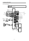
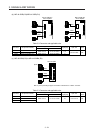
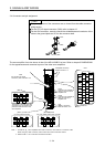
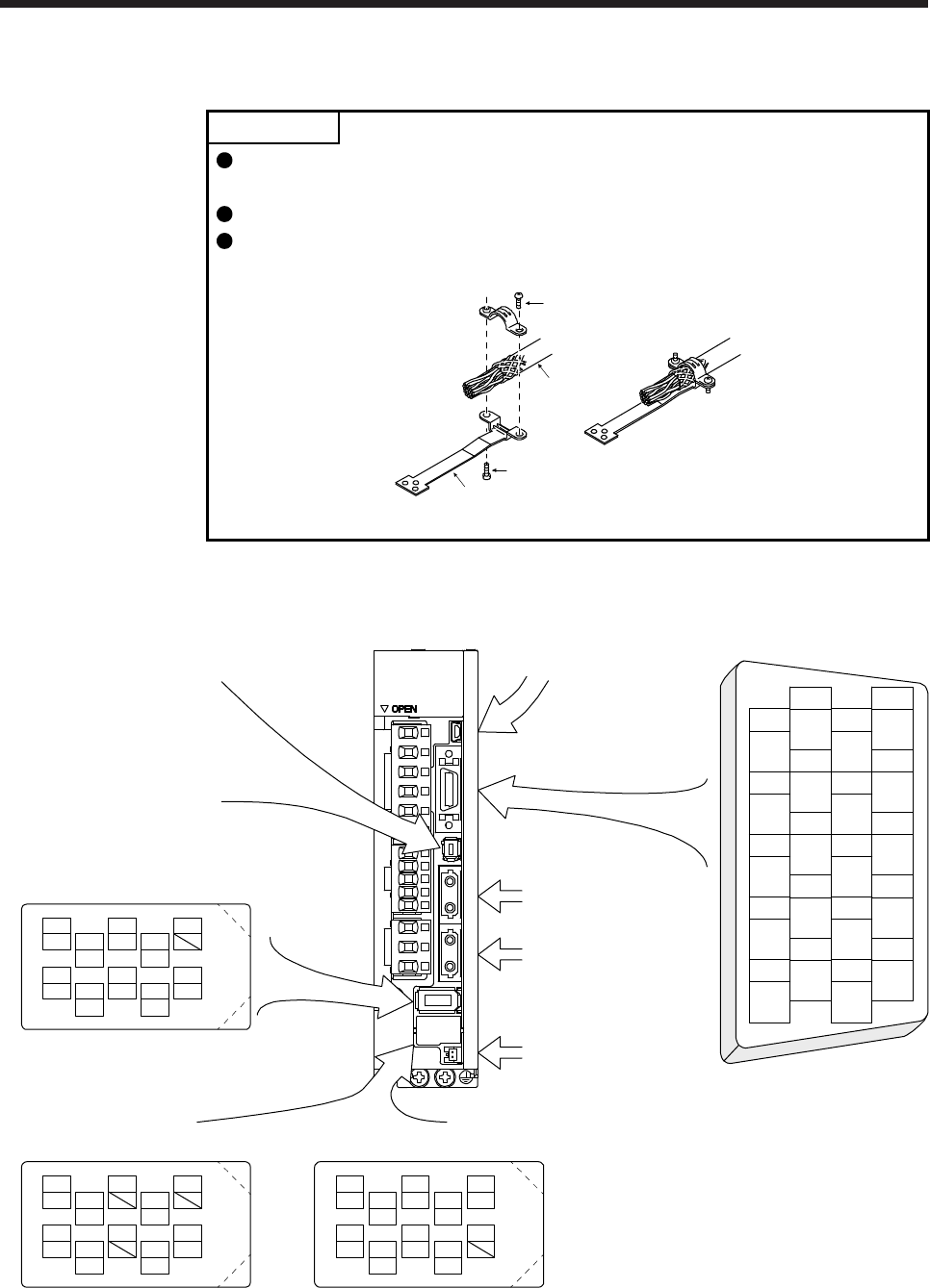
3.4 Connectors and pin assignment
POINT
The pin assignment of the connectors are as viewed from the cable connector
wiring section.
For the STO I/O signal connector (CN8), refer to chapter 13.
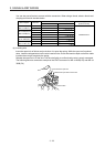
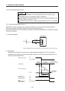
For the CN3 connector, securely connect the shielded external conductor of the
cable to the ground plate and fix it to the connector shell.
Screw
Screw
Ground plate
Cable
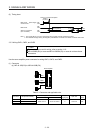
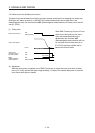
The servo amplifier front view shown is that of the MR-J4-20B-RJ or less. Refer to chapter 9 DIMENSIONS
for the appearances and connector layouts of the other servo amplifiers.
CN3
1
2
3
5
4
6
7
9
8
10
11
12
13
14
15
16
17
18
19
20
DI1
MO1
DICOM
LG
DOCOM
DICOM
LZ
DI2
MO2
EM2
LG
MBR
LBR
LA
LB
LZR
LAR
ALM
DI3INP
4
MRR
2
LG 8
6
1
P5
5
10
3
MR
7
9
BAT
MXR
MX
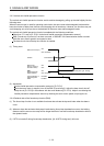
CN2
CN8
4
MRR2
2
LG 8
6
1
P5
5
10
3
MR2
7
9
MXR2
MX2
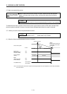
(Note1, 2) CN2L
4
PAR
2
LG 8
6
1
P5
5
10
3
PA
7
9
PB
PZR
PZ
PBR PSEL
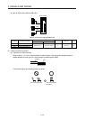
(for using serial encoder)
(Note 1, 2) CN2L
(for using A/B/Z-phase pulse encoder)
THM2
THM1
(Note 2)
CN5(USB connector)
Refer to section 11.7
The frames of the CN2 and CN3
connectors are connected to the
protective earth terminal in the
servo amplifier.
CN1A
Connector for SSCNET III
cable for previous servo
amplifier axis
CN1B
Connector for SSCNET III
cable for next servo
amplifier axis
CN4
(Battery connector)
Refer to section 11.8
For the STO I/O signal
connector, refer to section 13.2.
BAT
Note 1. The MR-J4-_B_ servo amplifiers have CN2L connectors. This CN2L is a connector of 3M.
When using any other connector, refer to each servo motor instruction manual.
2. Refer to table 1.1 for connections of external encoders.