


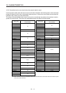

11. OPTIONS AND PERIPHERAL EQUIPMENT
11 - 3
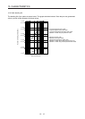
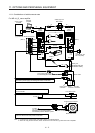
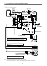
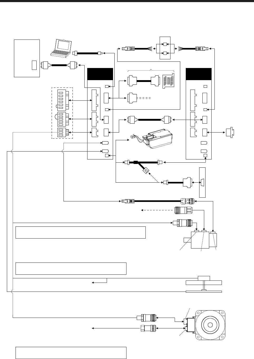
For MR-J4-_B_-RJ servo amplifier
6)
CN1A
CN1B
CN3
CNP1
CNP2
CNP3
CN1A
CN1B
CN2
CN3
7)
2) 3) 4)
5)
2) 3) 4)
CN2
CN8
CN5
CN8
CN5
CN4 CN4
8) 8)
CN9
CN10
CN2L CN2L
Refer to "Servo Motor Instruction Manual (Vol. 3)" for options for
servo motor power supply, electromagnetic brake, and encoder.
Refer to "Liner Encoder Instruction Manual" about options
for liner encoder.
Refer to "Direct Drive Motor Instruction Manual" about
options for direct drive motor power and encoder.
Servo
amplifier
Cap
(packed with the
servo amplifier)
(Note 1)
Servo system
controller
Personal
computer
1) (packed with the servo amplifier)
Servo
amplifier
(Note 2)
To 24 V DC power supply
for electromagnetic brake
Servo motor
Encoder
connector
Brake
connector
Power supply
connector
Liner servo motor
Liner encoder
Power supply connector
Direct drive motor
Encoder connector
To CN2
To CN2
The connection method changes
depending on incremental system
and absolute position detection system.
Safety logic uni
t
(Note 2)
MR-J3-D05
Battery
11)
10)
Battery unit
MR-BT6VCASE and
MR-BAT6V1 battery
Note 1. Connectors for 3.5 kW or less. For 5 kW or more, it is a terminal block.
2. When not using the STO function, attach the short-circuit connector ( 9)) came with a servo amplifier.