


APPENDIX
App. - 21
(7) Perform all risk assessments and safety level certification to the machine or the system as a whole.
It is recommended that a Certification Body final safety certification of the system be used.
(8) To prevent accumulation of multiple malfunctions, perform a malfunction check at regular intervals as
deemed necessary by the applicable safety standard. Regardless of the system safety level, malfunction
checks should be performed at least once per year.
(9) If the upper and lower power module in the servo amplifier are shorted and damaged simultaneously, the
servo motor may make a half revolution at a maximum. For a linear servo motor, the primary side will
move a distance of pole pitch.
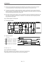
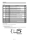
App. 5.5 Block diagram and timing chart
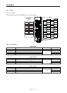
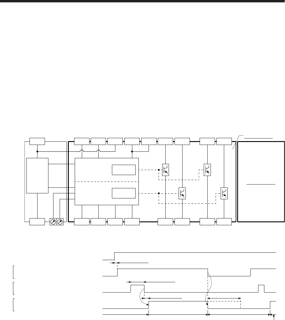
(1) Function block diagram
SDI1A- SDI2A- SDI1B- SDI2B- STO1A- STO2A- SDO1A- SDO2A-
SRESA+ SRESA- TOF1A TOF2A STO1A+ STO2A+ SDO1A+ SDO2A+TOFA
0 V
+24 V
DCDC
power
Safety logic
TIMER1
TIMER2
A-axis circuit
SW1 SW2
B-axis circuit
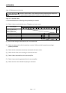
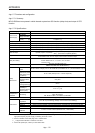
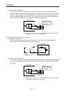
(2) Operation sequence
A-axis shutdown 1 and 2
B-axis shutdown 1 and 2
Energizing (close)
Shut-off (open)
Release (close)
Normal (open)
Normal (close)
Shut-off (open)
A-axis EMG start/reset
B-axis EMG start/reset
A-axis STO state 1 and 2
B-axis STO state 1 and 2
10 ms or shorter Shut off delay (SW1 and SW2) (Note)
STO status
Control enabled
STO status
50 ms or longer
SDI
SRES
STO
15 ms or longer
Power supply
Control enabled
Note. Refer to App. 5.10.
App. 5.6 Maintenance and disposal
MR-J3-D05 is equipped with LED displays to check errors for maintenance.
Please dispose this unit according to your local laws and regulations.