17. APPLICATION OF FUNCTIONS
17 - 49
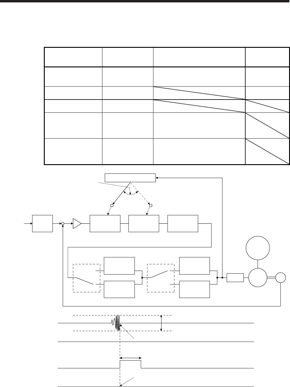
The following shows the function block diagram of the vibration tough drive function.
The function detects machine resonance frequency and compares it with [Pr. PB13] and [Pr. PB15], and
reset a machine resonance frequency of a parameter whose set value is closer.
Filter Setting parameter Precaution
Parameter that is
reset with vibration
tough drive function
Machine resonance
suppression filter 1
PB01/PB13/PB14 The filter can be set automatically with
"Filter tuning mode selection" in [Pr.
PB01].
PB13
Machine resonance
suppression filter 2
PB15/PB16 PB15
Machine resonance
suppression filter 3
PX17/PX18
Machine resonance
suppression filter 4
PX19/PX20 Enabling this filter disables the shaft
resonance suppression filter.
The shaft resonance suppression filter is
enabled for the initial setting.
Machine resonance
suppression filter 5
PX21/PX22 Enabling the robust filter disables the
machine resonance suppression filter 5.
The robust filter is disabled for the initial
setting.
Command
pulse train
Command
filter
Encoder
Servo motor
PWM
M
Load
+
-
Machine
resonance
suppression
filter 1
[Pr. PB13] [Pr. PB15] [Pr. PX17]
Machine
resonance
suppression
filter 2
Machine
resonance
suppression
filter 3
Machine
resonance
suppression
filter 4
Machine
resonance
suppression
filter 5
Shaft
resonance
suppression
filter
Robust filter
[Pr. PX19]
[Pr. PX21]
[Pr. PB17]
[Pr. PX20] [Pr. PX31]
Updates the parameter
whose setting is the
closest to the machine
resonance frequency.
Vibration tough drive
Torque
ALM
(Malfunction)
WNG
(Warning)
MTTR
(During tough drive)
ON
OFF
[Pr. PX26 Vibration tough drive - Oscillation detection level]
Detects the machine resonance and reconfigures the filter automatically.
During tough drive (MTTR) is not turned on in the vibration tough drive function.
ON
OFF
ON
OFF
5 s


