


Bosch Security Systems | 2011-02
Praesideo 3.5 | Installation and User Instructions | 3 | Control Equipment en | 96
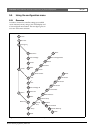
5.6 Configuration and operation
5.6.1 Introduction
The next sections give descriptions of the possible
configuration options. Each description is followed by
the relevant menu items with detailed instructions per
menu option. The default values are indicated by an
asterisk (*) when applicable.
5.6.2 Start-up
When the network controller is (re)started, the display
shows the name of the unit and the clock (first of the
status screens).
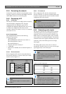
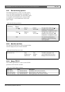
5.6.3 Status screens
The status screens (see table 5.7) provide general
information about the network controller.
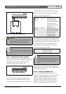
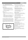
5.6.4 Emergency menu
The Emergency ... item (see figure 5.12) provides access to
the emergency menu. This menu is automatically
activated when the system is put into the emergency
state. It changes automatically back to the Clock screen
when the emergency state is reset. The Emergency ...
menu screen itself shows the name of key that was used
to activate the emergency state or the IP address of the
open interface controller that activated the emergency
state. For example:
In this example, Emergency indicates that the emergency
state is active and that it was activated by button
CST-EM-PTT.
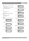
The menu items in the emergency menu provide
additional information about the emergency state and
allow to acknowledge and reset the emergency state (see
table 5.8). When the emergency state is reset, all
emergency calls are aborted.
5.6.5 Faults menu
The Faults ... menu (see figure 5.12) provides access to
the faults menu. This menu is automatically activated
when there is a fault in the system. Because the number
of active faults in the system can vary, the item numbers
in this menu are not fixed. The youngest fault is the fault
with the lowest number. The maximum number of
faults is 200.
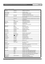
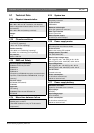
table 5.7: Status screens
Menu item Description
Clock Shows the name of the unit and
the time and date.
VU Meter Visual indication of the signal
strengths on all audio inputs and
audio outputs of the network
controller.
Emergency ...
CST-EM-PTT
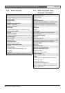
table 5.8: Emergency menu
Menu item Description
1 Date/Time Date and time on which the
emergency state was activated.
2 Acknowledge Acknowledges the emergency
state.
3 Reset Resets the emergency state.
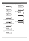
Note
When a new fault occurs while another fault is
being viewed, the item number of the fault that
is being viewed is automatically incremented.
For example, when 23 Overload is being viewed
while a new fault occurs, it becomes
automatically 24 Overload.
Note
When fault 200 is being viewed while a new
fault occurs, fault 200 is automatically deleted
and replaced by the next fault. For example,
fault 200 is 200 Overload and the next fault is
199 Gnd Short. Then 200 Overload
automatically becomes 200 Gnd Short when a
new fault occurs.