


Bosch Security Systems | 2011-02
Praesideo 3.5 | Installation and User Instructions | 3 | Control Equipment en | 90
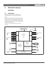
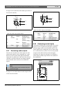
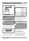
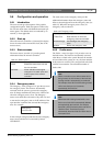
5.3.9 Connecting control outputs
The network controller has 5 control outputs. The
control outputs can be used to send signals to third party
equipment to trigger actions. Each control output
connection has three pins (see figure 5.10).
The common (C) pin of the control output should
always be connected. Whether the other pin that is
connected is the normally closed (NC) or normally
open (NO) depends on which action that has to take
place when the control output is active (see table 5.5).
In the configuration, a purpose must be attached to the
control output that indicates the action to be taken when
it becomes active (see table 43.6). Control outputs 4 and
5 of network controllers of version HW15/xx and
higher already have a fixed purpose (see table 5.6).
See section 32.9 for instructions about connecting an
audible indicator (buzzer) to the control outputs for fault
and emergency notifications.
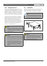
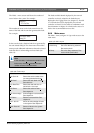
5.3.10 Connecting RS232 port
The network controller has a RS232 connector for
production and development purposes. Do not use this
connector in installed Praesideo systems, with the
following exception. The PRS-NCO-B comes with a
dedicated buzzer for audible fault and voice alarm
notifications. This buzzer comes with a connector to
power it from the RS232 port. See section 32.9.
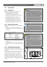
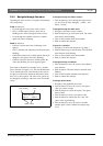
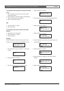
figure 5.9: Non-supervised control input
Warning
Do not connect DC or AC signals to the control
inputs, otherwise the input circuit may be
damaged. Only use voltage-free contacts.
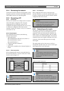
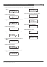
Note
Do not combine control input wires of multiple
control inputs (e.g. do not use a common return
wire).
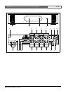
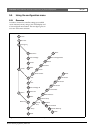
figure 5.10: Control outputs
Control In
12345678
C NCNO C NC NO C NCNO C NC NO C NC NO
Control Out
1 2 3 4 5
table 5.5: Control outputs details
Connection Abbr. Description
Normally
closed
NC By default, the NC
contact is connected
with common contact C.
When the output is
activated, the NC contact
is opened.
Normally
open
NO By default, the NO
contact is not connected
with common contact C.
When the output is
activated, the NO
contact is closed.
table 5.6: Control outputs 4 and 5
Control output Purpose
4 Audible fault indicator
5 Visual fault indicator
Note
For fail-safe behavior, these fixed control outputs
are energized in the default (faultless) situation,
so NC is open and will be closed if a fault
occurs.