


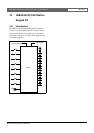
Bosch Security Systems | 2011-02
2011-02 | Installation and User Instructions | 5 | Call Stations en | 222
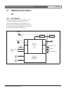
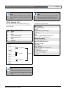
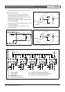
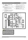
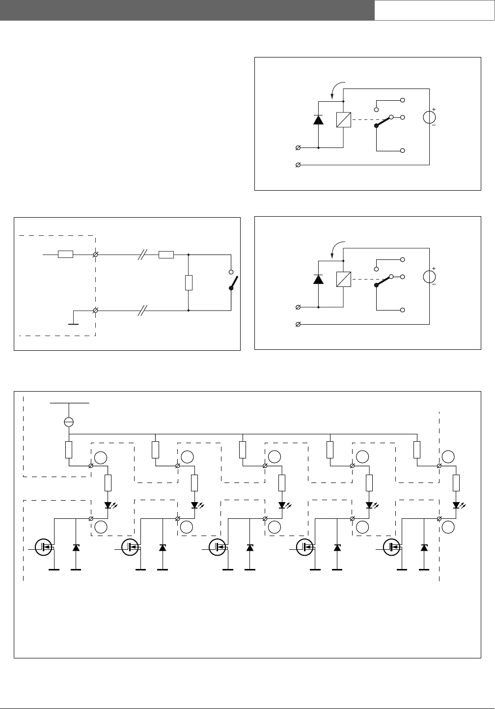
It is possible to connect the following to the control
inputs/outputs connector:
• Press-to-talk (PTT) key. See figure 18.8 for a
connection diagram. The two resistors must be
placed in the circuit, because the contact is always
supervised by the system software.
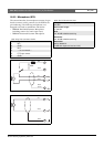
• Internally powered lamp or LED. See figure 18.9 for
a connection diagram.
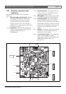
• Externally powered lamp or LED. See figure 18.9 for
a connection diagram.
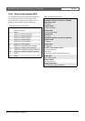
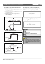
• Externally powered relay. See figure 18.11 for a
connection diagram.
figure 18.8: Press-to-talk (PTT) key
figure 18.9: Internally powered LED
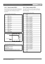
GND
5V
PTT Input
Contact
10 kΩ
10 kΩ
10 kΩ
+5V, 30 mA
62V 62V
R2
3
4
6
8
7
10
9
12
11
5
R1
PI FI CI SPI SEI
R1
R2
62V
R1
R2
62V
R1
R2
62V
R1
R2
PI
FI
CI
SPI
SEI
= Power Indicator
= Fault Indicator
= Call Indicator
= System Priority Indicator
= System Emergency Indicator
R1 = 0 Ω, R2 = 330 Ω (HW07/04 and later)
R1 = 180 Ω, R2 = 150 Ω (HW07/00 to HW07/03)
R1 = 330 Ω, R2 = 0 Ω (before HW07/00)
figure 18.10: Externally powered relay
figure 18.11: Externally powered relay
Max. 56V
I < 100 mA
Output X, IN
GND
Max. 56V
I < 100 mA
Output X, IN
GND