


Bosch Security Systems | 2011-02
Praesideo 3.5 | Installation and User Instructions | 4 | Amplifiers en | 177
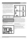
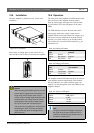
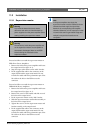
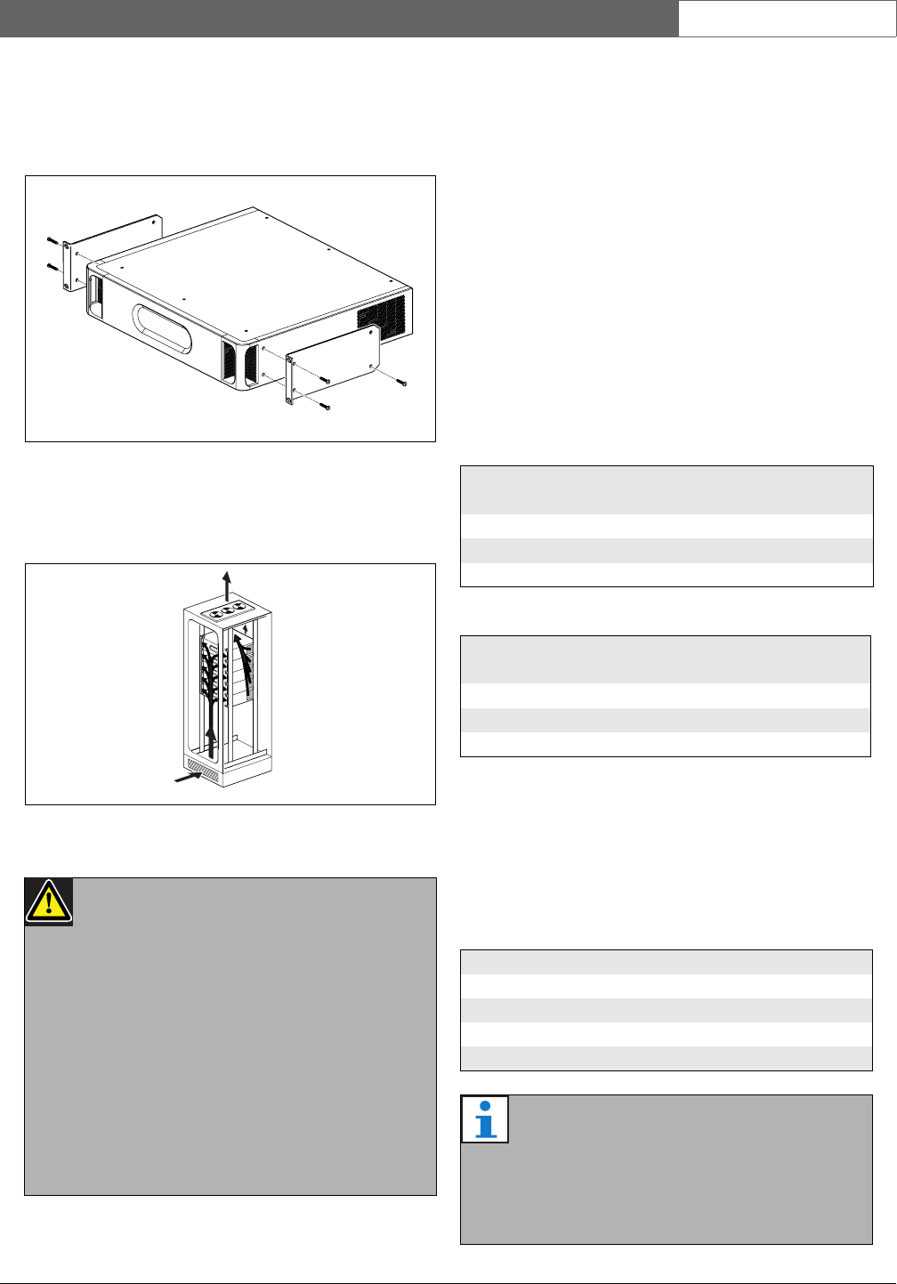
10.5 Installation
The basic amplifier is suitable for only 19-inch rack
installation.
Ensure there is enough space for the cool air flow to
enter and the warm air flow to leave the basic amplifier.
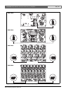
10.6 Operation
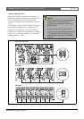
The front panel of the amplifier has LED indicators that
show the status of the amplifier channels, battery
back-up, mains supply and supervision. See the table
10.5 and table 10.6 for the descriptions of the status
LEDs.
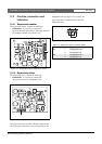
The LED indicators will show the fault status of the
mains supply and battery supply if supervision is
enabled with the supervision switches (9 in figure 10.2).
This status is always transferred to the multi channel
interface, even if the switches are in the Off-position.
The switches only control the LED indicators, e.g. for
stand-alone use.
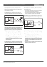
The amplifier channel LED indicators show the status of
each amplifier channel independently. Each channel
has four indicators, one yellow and three green. See
table 10.7 for the descriptions of the status LEDs for the
amplifier channels.
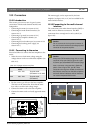
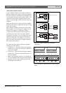
figure 10.17: Installation
figure 10.18: Air flow in a 19" rack
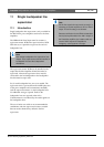
Caution
When mounting the brackets to the unit, use the
screws that are supplied with the brackets, four
longer ones and two shorter ones. Use two
screws of 7.5 mm thread length at the front side
of each bracket, use a short screw of 5.2 mm
thread length at the rear side of each bracket.
Do not use screws with a thread length of
>10 mm for the front positions or screws with a
thread length of >5.7 mm at the rear postion;
longer screws may touch or damage internal
parts of the unit.
table 10.5: Mains LED status
Mains
LED
Mains Mains supervision
enabled
Green Present X
Ye ll o w Not present Enabled
Off Not present Off
table 10.6: Battery LED status
Battery
LED
DC back-up DC back-up supervi-
sion enabled
Green Present X
Ye ll o w Not present Enabled
Off Not present Off
table 10.7: Channel LED status
Channel LED status Output level
Yellow 0 dB / Fault *
Green - 6 dB
Green - 12 dB
Green - 20 dB
Note
The yellow channel LED indicates clipping of
the signal when the green LEDs are also on,
otherwise it indicates a fault situation such as
overheat or a short circuit.