


Bosch Security Systems | 2011-02
2011-02 | Installation and User Instructions | 5 | Call Stations en | 221
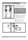
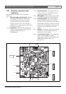
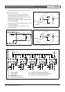
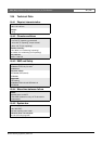
18.2.4 Control input/outputs (X80)
The call station kit provides an external interface for
one control input and five control outputs. This
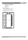
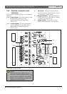
external interface consists of a pin header with 14
positions (see the PCB for the pin numbering).
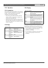
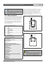
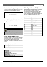
table 18.7: X80 connector details
Pin Signal
1 PTT input contact
2 GND
3 Output 1, out (power indicator)
4 Output 1, in (power indicator)
5 Output 2, out (fault indicator)
6 Output 2, in (fault indicator)
7 Output 3, out (call indicator)
8 Output 3, in (call indicator)
9 Output 4, out (system priority indicator)
10 Output 4, in (system priority indicator)
11 Output 5, out (system emergency indicator)
12 Output 5, in (system emergency indicator)
13 GN D
14 GND
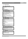
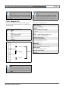
table 18.8: X80 technical data
PTT input contact
Resistance detection (supervision enabled):
Cable short circuit
< 2.5 kohm
Contact closed
7. 5 k o h m to12 kohm
Contact open
17. 5 k o h m to 22 kohm
Cable broken
> 27 kohm
Resistance detection (supervision disabled):
Contact closed
< 12 kohm
Contact open
> 17.5 ko h m
Internal output supply current:
max. 10 mA (per pin)
max. 30 mA
(in total max. 3 LEDs are simultaneously on)
Output type:
open collector/drain
Output voltage:
max. 56 V (per pin)
Output sink current:
max. 100 mA per output switch pin