


Bosch Security Systems | 2011-02
Praesideo 3.5 | Installation and User Instructions | 6 | Installation Accessories en | 263
25 PRS-NSP Network
Splitter
25.1 Introduction
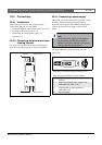
The PRS-NSP Network Splitter is used to create
short-circuit proof tap-off points in the network. A
network may contain up to 10 network splitters.
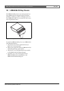
This unit in metal housing is the successor of the
LBB4410/00 in plastic housing.
25.2 Controls and connectors
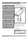
25.2.1 Exterior
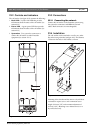
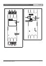
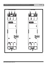
The exterior of the network splitter (see figure 25.2)
contains the following:
1 External power supply - A connection for an
(optional) external power supply. The external power
supply only feeds the tap-offs (see section 25.3.3).
2 Tap-off 1 - A system bus connector for creating a
tap-off. The tap-off is protected against short-circuits
and has a maximum load of 2.5 A (see
sections 25.2.2 and 25.3.2).
3 System bus - A system bus connector for looping
through the main branch (see section 25.3.2).
4 Lid - A lid that provides access to the jumpers (see
section 25.2.2). The rear side of the lid contains a
label with explanation about the internal settings.
5 Fault LED - A yellow fault LED that provides
information about the status of the network splitter
(see section 25.5).
6 Power LED - A green power LED that provides
information about the status of the network splitter
(see section 25.5).
7 Tap-off 2 - A system bus connector for creating a
tap-off. The tap-off is protected against short-circuits
and has a maximum load of 2.5 A (see
sections 25.2.2 and 25.3.2).
8 System bus - A system bus connector for looping
through the main branch (see section 25.3.2).
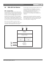
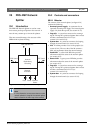
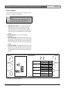
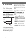
figure 25.1: Block diagram of the network splitter
Note
It is not allowed to connect more than two other
network splitters to a tap-off of a network splitter
that is located in the main loop of the network.
Network
Processor
POF (main)
POF (tap-offs, 2x)
Fault Power External
Power
Network
Redundancy
Switching
POF (main)