


Bosch Security Systems | 2011-02
Praesideo 3.5 | Installation and User Instructions | 7 | System Hardware Installation en | 295
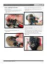
31 Cabling
31.1 Introduction
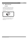
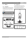
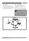
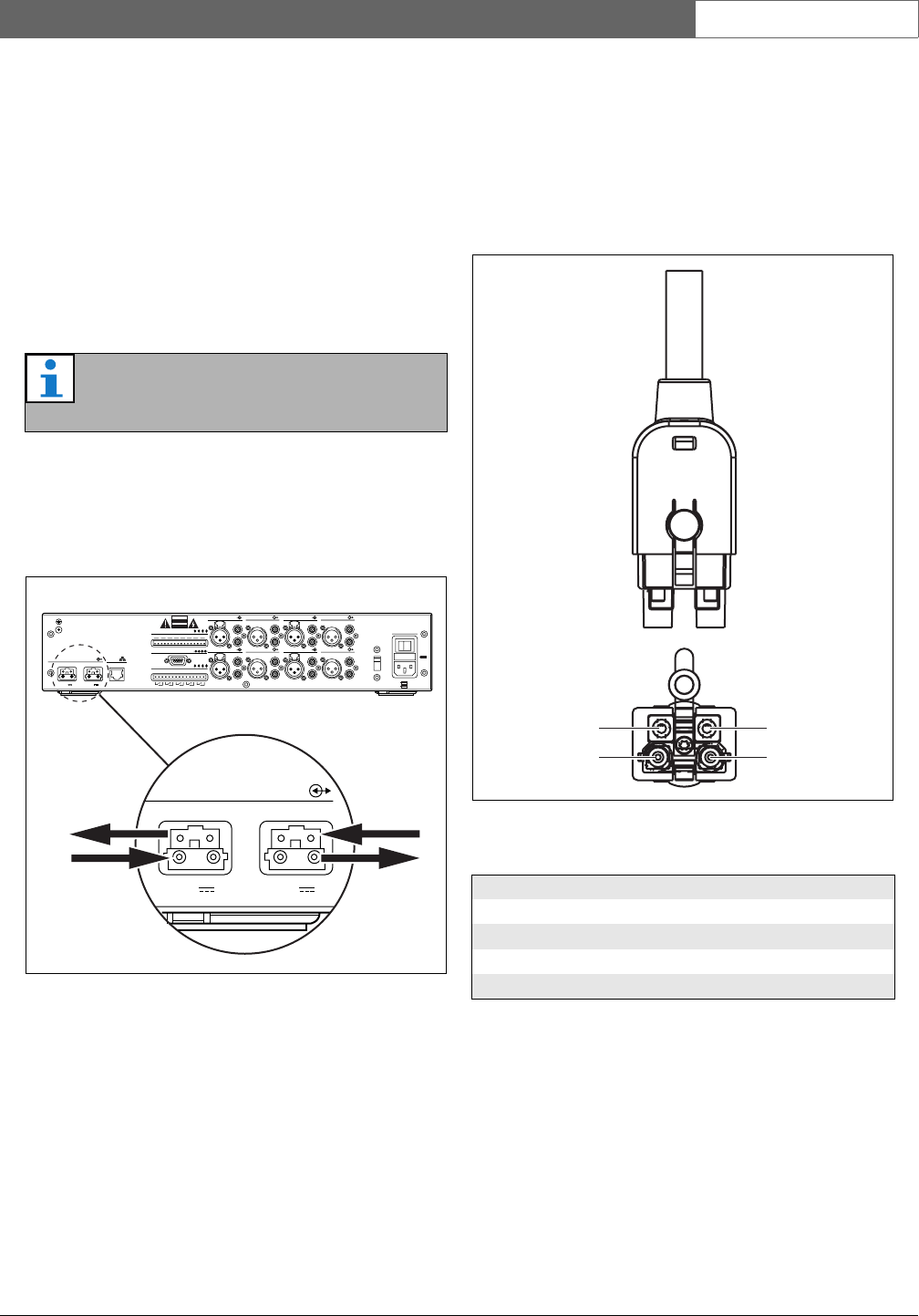
The pieces of equipment in a Praesideo system form a
daisy chain. Therefore, all units are equipped with two
interchangeable system bus connectors (see figure 31.1).
Use one of these connectors to connect a unit to the
previous unit and the other to connect it to the next unit
in the chain.
Because the units are daisy-chained, it is possible to add
or remove equipment anywhere in the network without
affecting the performance of other units, provided that
the other network connection remains available.
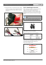
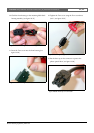
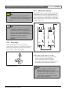
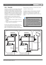
31.2 System bus
A system bus cable (see figure 31.2) has two plastic
optical fiber (POF) ‘wires’ and two copper wires. The
POF wires can transport up to 28 simultaneous audio
channels and Praesideo control data, whereas the
copper wires transport power to feed the units.
Note
Both system connectors are identical.
l
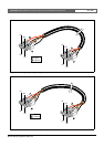
figure 31.1: Daisy chain
Network Ethernet
Control In
Audio In 3
12345678
CNC NO CNC NOC NC NOCNC NO CNC NO
12
48V
Audio Out 3 Audio In 4 Audio Out 4
Audio In 1 Audio Out 1 Audio In 2 Audio Out 2
115: 100-120V~ 50-60Hz
Mains
T2.5A 250V
Control Out
RS 232
1 2 3 4 5
48V
Avis
Caution
Risk of electric shock.
Do not open.
Risk of electric shock.
Do not open.
230
OI
230: 220-240V~ 50-60Hz
T1.25A H 250V
12
48V
48V
l
figure 31.2: System bus connector
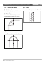
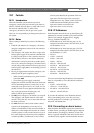
table 31.1: System bus cable details
Number Color Material Description
E1 Red Copper Power, + (48V)
E2 Brown Copper Power, - (GND)
O1 Black POF Data
O2 Black POF Data
O1
E1
O2
E2