


Bosch Security Systems | 2011-02
Praesideo 3.5 | Installation and User Instructions | 4 | Amplifiers en | 175
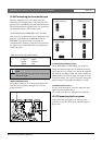
The back-up supply can be supervised by the basic
amplifier (see figure 10.2, no. 9) and is available for the
multi channel interface.
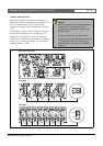
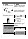
10.4 Fan control
The PRS-1B500, PRS-2B250, PRS-4B125 and
PRS-8B060 amplifiers, from HW version 06/00
onwards, have a fan monitoring circuit that detects the
actual fan rotation. This detection is needed for
compliancy to the standards UL864 and UL1711, for
use in the USA. Additionally the internal fans need to
run at full speed for compliancy to these standards. A
jumper on the main PCB selects between two positions:
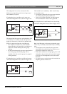
• Normal (factory default) - The fans are temperature
controlled, normally running at low speed and
switching to high speed in case the temperature
exceeds a certain level. Fan monitoring is not
activated.
• Full speed - The fans run at full speed continuously.
Fan monitoring is activated. Do not enable Switch
amplifiers to standby (see section 44.4) for this
selection, because in standby the fans are stopped
and a fault would be generated.
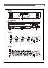
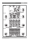
For the PRS-1B500, the jumper is indicated on the PCB
as X652; connection 1-2 selects Normal, connection 2-3
selects Full speed. See figure 10.16.
For the PRS-2B250, the jumper is indicated on the PCB
as X652 and X653 (one for each fan); connection 1-2
selects Normal, connection 2-3 selects Full speed. See
figure 10.16.
For the PRS-4B125, the jumper is indicated on the PCB
as X88 and X91 (one for each fan); connection 1-2
selects Normal, connection 2-3 selects Full speed. See
figure 10.16.
For the PRS-8B060, the jumper is indicated on the PCB
as X88 and X91 (one for each fan); connection 1-2
selects Normal, connection 2-3 selects Full speed. See
figure 10.16.
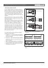
Warning
For safety reasons you must use an external
circuit breaker. Install in accordance with the
local Electrical and Building Code, e.g. for USA
and Canada in accordance with NEC/CEC and
for Germany in accordance with VDE0108-1.
To reduce the risk of electric shock do not
perform any servicing other than that contained
in the operating instructions unless you are
qualified to do so. See section 1.2 Intended
audience.
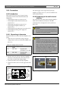
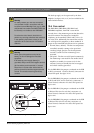
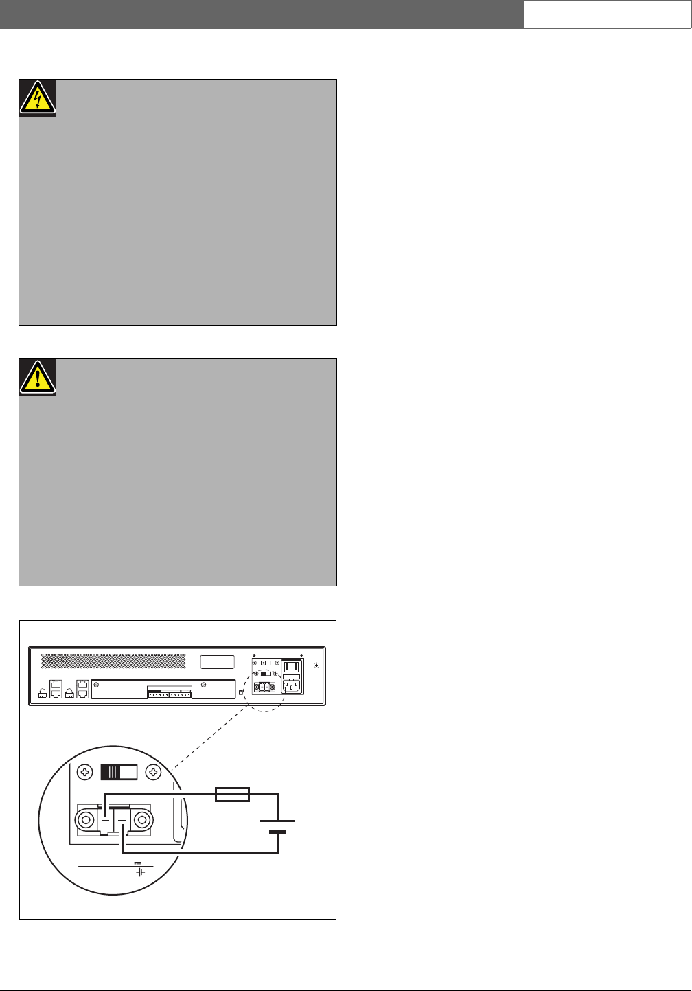
Warning
Never ground the positive terminal of the
battery, as this will damage the Praesideo
equipment.
If the back-up power supply (battery) is
grounded, always connect the negative terminal
(0) first and the positive terminal (+) second.
Disconnect in reverse order: disconnect the
positive terminal first and the negative terminal
second. This avoids excessive ground loop
currents.
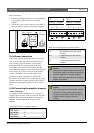
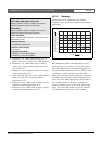
figure 10.15: Connecting back-up supply
Battery
48V 12A
Non-isolated input
0
+
48V
15AT