


Bosch Security Systems | 2011-02
2011-02 | Installation and User Instructions | 5 | Call Stations en | 247
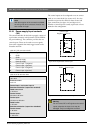
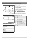
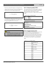
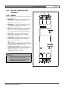
The value of resistor R in figure 21.10 depends on the
voltage of the external source, the forward voltage of the
LED and the current flowing through the LED:
For example, the voltage of the external source is 24 V,
the forward voltage of the LED is 2 V and the current
flowing through the LED is 10 mA, then:
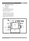
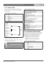
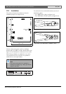
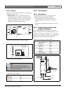
21.2.5 External speaker (X511)
The external interface for external speakers consists of a
pin header connector with 6 positions (see the PCB for
the pin numbering.) When using an external
loudspeaker, also connect a volume control (see section
21.2.2).
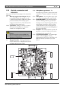
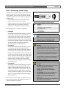
21.2.6 Keypad interface (X1)
The external interface for the keypad (kits) consists of an
IDC connector with 16 positions. Keypads are
connected in series. That means there is only a direct
connection between the remote call station kit and the
first keypad. The second keypad is connected to the
first, the third to the second etc. using standard flat
cables.
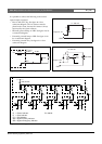
Warning
Do not connect DC or AC signals to the control
inputs, otherwise the input circuit may be
damaged. Only use voltage-free contacts.
R
V
source
V
forward
–
I
---------------------------------------------=
R
24 2–
10 10
3–
⋅
--------------------- 2 2 00 Ω()==
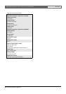
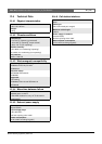
table 21.9: X511 connector details
Pin Signal
1, 2, 3 Speaker +
4, 5, 6 Speaker -
table 21.10: X511 technical data
Impedance:
8 to 32 ohm
Signal/Noise ratio:
typical 80 dB ± 3 dB at max. output
Output power:
typical 100 mW, max. 300 mW
table 21.11: X1 connector details
Pin Signal
1 Synchronization line.
2 GND
3 Interrupt line (INT)
4 GND
5 Data I2C (SDA)
6 GND
7 Clock I2C (SCL)
8 GND
9Power
10 GND
11 Po we r
12 GND
13 Power
14 GND
15 Power
16 GND