


Bosch Security Systems | 2011-02
2011-02 | Installation and User Instructions | 5 | Call Stations en | 244
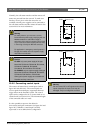
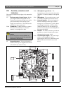
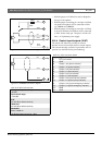
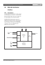
• With the jumper on X300 the kit can be adapted to
the type of microphone.
• With the jumper connecting pin 1 and pin 2 of X300,
a dynamic microphone can be connected to X301,
e.g. LBB9081 and LBB9082.
• With the jumper connecting pin 2 and pin 3 of X300,
an electret condenser microphone can be connected
to X301. In this mode, pin 1 and pin 3 of X301 will
have a 12 V phantom power supply.
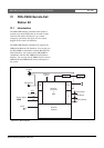
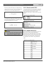
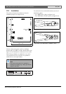
21.2.4 Control input/outputs (X107)
The remote call station kit provides an external
interface for one control input and five control outputs.
This external interface consists of a pin header with 14
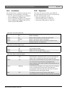
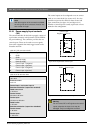
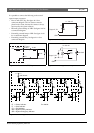
positions (see the PCB for the pin numbering).figure 21.6: LBB9081 connection diagram
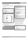
figure 21.7: LBB9082 connection diagram
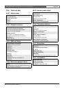
table 21.6: X301 technical data
Microphone input sensitivity:
-50 dBV
Input control range:
-7 to 8 dB
S/N:
min. 60 dB at default sensitivity
Headroom:
min. 30 dB at default sensitivity
Bandwidth:
340 to 14000 Hz
(-3 dB with respect to level at 1 kHz)
10kΩ
10kΩ
blue
black
red
white
black
(thick)
5
6
3
1
2
1
3
2
black
white
red
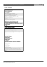
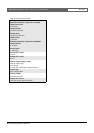
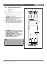
table 21.7: X107 connector details
Pin Signal
1 PTT input contact
2 GND
3 Output 1, out (power indicator)
4 Output 1, in (power indicator)
5 Output 2, out (fault indicator)
6 Output 2, in (fault indicator)
7 Output 3, out (call indicator)
8 Output 3, in (call indicator)
9 Output 4, out (system priority indicator)
10 Output 4, in (system priority indicator)
11 Output 5, out (system emergency indicator)
12 Output 5, in (system emergency indicator)
13 GN D
14 GND