


Bosch Security Systems | 2011-02
Praesideo 3.5 | Installation and User Instructions | 3 | Control Equipment en | 120
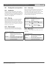
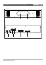
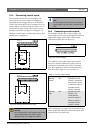
7.2 Controls and connectors
7. 2 .1 Fron t v i e w
The front of the CobraNet interface (see figure 7.2)
contains the following:
1 Menu display - A 2x16 character LCD display
gives information about the CobraNet interface (see
section 7.7).
2 Menu button - A turn-and-push button to operate
the menu (see section 7.7).
3 Monitoring headphones output - A 3.5 mm
(0.14 inch) jack socket to connect the headphones for
audio monitoring purposes.
7.3 Rear view
The rear of the CobraNet interface (see figure 7.2)
contains the following:
4 System bus - Two system bus connectors to
connect the CobraNet interface to other Praesideo
equipment (see section 7.4.2)
5 CobraNet interface - Two RJ45 sockets to
connect the CobraNet interface to the CobraNet
network (see section 7.4.3)
6 Control inputs - The control inputs can be used to
receive signals from third party equipment that must
trigger actions in the Praesideo network (see
section 7.4.4).
7 Control outputs - The control outputs can be used
to send signals to third party equipment to trigger
actions generated by the Praesideo network (see
section 7.4.5).
7.4 Connections
7.4.1 Introduction
This section gives an overview of typical system
connections using the CobraNet interface.
• Connecting the Praesideo network (see section 7.4.2).
• Connecting the CobraNet network (see
section 7.4.3).
• Connecting control inputs (see section 7.4.4).
• Connecting control outputs (see section 7.4.5).
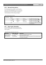
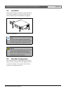
7.4.2 Connecting the Praesideo
network
Connect the CobraNet interface to the Praesideo system
using the system bus connectors and LBB4416 network
cables. Both connectors are interchangeable.
This unit is powered by the network controller, via the
Praesideo system bus.
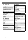
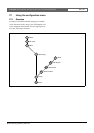
7.4.3 Connecting the CobraNet
network
Connect the CobraNet interface to the CobraNet
network using the Ethernet connectors and Cat-5
Ethernet cables. Use either one Cat-5 connection for a
normal Ethernet connection or two for a redundant
connection. Ethernet supports redundant connections
between switches using self-healing topologies. Each
connection has two indicators:
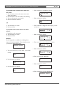
• The right indicator shows green for Ethernet link
and flashing green for Ethernet activity.
• The left indicator lights yellow on the port in use and
flashes yellow on the port in use if the interface is the
conductor.