


Bosch Security Systems | 2011-02
2011-02 | Installation and User Instructions | 5 | Call Stations en | 218
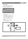
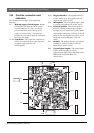
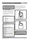
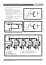
18.2.1 Back-up supply (X4)
The external interface for the back-up supply consists of
a pin header connector with 8 positions (see the PCB for
the pin numbering). The connector provides also two
control inputs. These can be used to receive signals
from other equipment. For example, signals from the
back-up supply that indicate its status such as mains
available, battery OK etc.
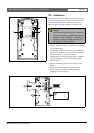
The control inputs can be configured to act on contact
make or on contact break (see section 42.5). It is also
possible to supervise the cables for short-circuits and
open connections (see figure 18.3 and figure 18.4).
Whether a control input is actually supervised or not is
defined in the configuration.
Note
With the exception of the connection to X1 and
X2, the wiring of all other connectors must be
less than 3 meter in length..
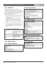
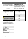
table 18.1: X4 connector details
Pin Signal
1GND
2 GND
3 Back-up supply
4 Back-up supply
5GND
6 Control input 1
7GND
8 Control input 2
table 18.2: X4 technical data
Backup voltage:
18 t o 56 V(DC )
No fault reporting when > 20 V
Backup current:
max. 2 A
Control input 1 and control input 2
Resistance detection (supervision enabled):
Cable short circuit
< 2.5 kohm
Contact closed
7. 5 k o h m to12 kohm
Contact open
17. 5 k o h m to 22 kohm
Cable broken
> 27 kohm
Resistance detection (supervision disabled):
Contact closed
< 12 kohm
Contact open
> 17.5 ko h m
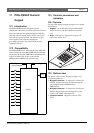
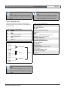
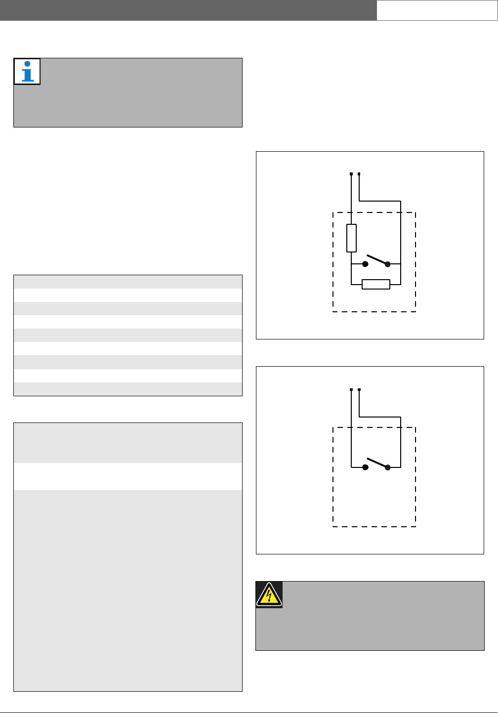
figure 18.3: Supervised control input
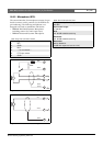
figure 18.4: Non-supervised control input
Warning
Do not connect DC or AC signals to the control
inputs, otherwise the input circuit may be
damaged. Only use voltage-free contacts.
10kΩ
10kΩ
GND Control input
GND Control input