


Bosch Security Systems | 2011-02
2011-02 | Installation and User Instructions | 5 | Call Stations en | 253
22.3.3 Connecting a power supply
Normally, the call station interface and the remote call
station are powered from the Praesideo network. It is
also possible to power the remote call station and the
call station interface from external power supplies. For
example, when:
• The call station interface is connected to a fiber
interface without external power supply.
• The cable between the remote call station and call
station interface is long and many call station
keypads are connected to the remote call station.
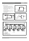
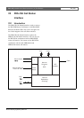
The following power concepts are supported:
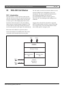
• Concept I
The call station interface takes the DC power from
the Praesideo network to power itself and the
connected remote call station. When the voltage on
the Praesideo network drops below 18 V(DC), the
call station interface and the remote call station take
the DC power from the external power supply of the
call station interface. The Jumper settings are
described in figure 22.4 and table 22.1.
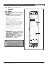
• Concept II
The call station interface takes the DC power from
the Praesideo network to power itself and the
connected remote call station. When the voltage on
the Praesideo network drops below 18 V(DC), the
call station interface and the remote call station take
the DC power from the external power supply of the
remote call station. The external power supply of the
remote call station is the back-up power supply for
both the remote call station and the call station
interface. The Jumper settings are described in figure
22.4 and table 22.1.
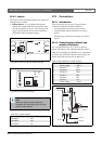
• Concept III
The call station interface takes the DC power from
the Praesideo network to power itself. When the
voltage on the Praesideo network drops below 18
V(DC), the call station interface takes the DC power
from its external power supply. In this concept, the
remote call station always has its own external power
supply. The Jumper settings are described in figure
22.4 and table 22.1.
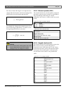
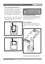
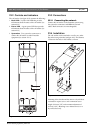
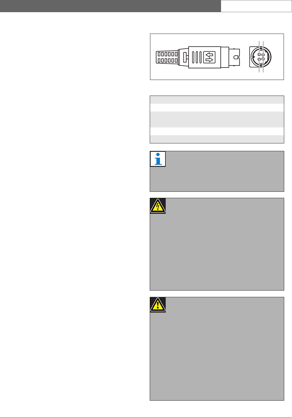
The remote call station and the call station interface are
delivered with a separate Kycon KPP4-P connector to
connect external power supplies.
figure 22.6: Connection diagram (external view)
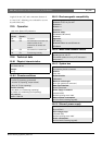
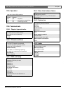
table 22.3: Kycon KPP-4P connector details
Pin Signal
1 Ground
2 Power from local power supply
(max. 48 V/1.2 A)
3 Input contact 1
4 Input contact 2
Note
The pin numbers are also indicated on the inside
of the connector. For detailed connector
assembly instructions, see appendix B.
Warning
For safety reasons, you must use a current
limited external power supply complying with the
60065 standard for audio/video usage or
equivalent, with a maximum output current of 5A,
or you must use an external fuse (5A max, slow)
in the wiring to the Kycon KPP-4P connector.
For application in emergency sound systems in
Europe, the installer must use a power supply
with EN54-4 certification.
Caution
For USA: only use a power supply of the type
Mean Well PLN-30-24, PLN-30-36,
PLN-30-48, PLN-60-24, PLN-60-36,
PLN-60-48, PLN-100-24, PLN-100-36 or
PLN-100-48.
For CANADA: only use a power supply of the
type Mean Well PLN-30-24, PLN-30-36,
PLN-60-24, PLN-60-36, PLN-100-24 or
PLN-100-36.
Other types of power supply are not tested with
Praesideo and may cause harm.
42
31