


Bosch Security Systems | 2011-02
Praesideo 3.5 | Installation and User Instructions | 3 | Control Equipment en | 108
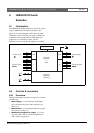
6.3 Connections
6.3.1 Introduction
This section gives an overview of typical system
connections using the audio expander.
• Connecting the network (see section 6.3.2).
• Connecting audio inputs (see section 6.3.4).
• Connecting audio outputs (see section 6.3.4).
• Connecting control inputs (see section 6.3.5).
• Connecting control outputs (see section 6.3.6).
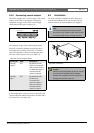
6.3.2 Connecting the network
Connect the audio expander to the Praesideo system
using the system bus connectors and LBB4416 network
cables. Both connectors are interchangeable.
This unit is powered by the network controller, via the
Praesideo system bus.
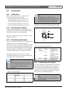
6.3.3 Connecting audio inputs
The audio expander has 4 audio inputs to interface with
analog audio sources. Each audio input has two
connectors on the rear of the audio expander; one XLR
connector (for balanced signals) and one double cinch
connector (for unbalanced signals). The audio expander
mixes stereo signals connected to the cinch connectors
of the same audio input into one single mono signal.
The analog audio can be a line source as well as a
microphone. See table 6.1 for an overview of the input
types supported by each of the inputs.
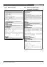
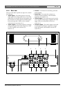
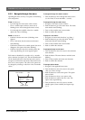
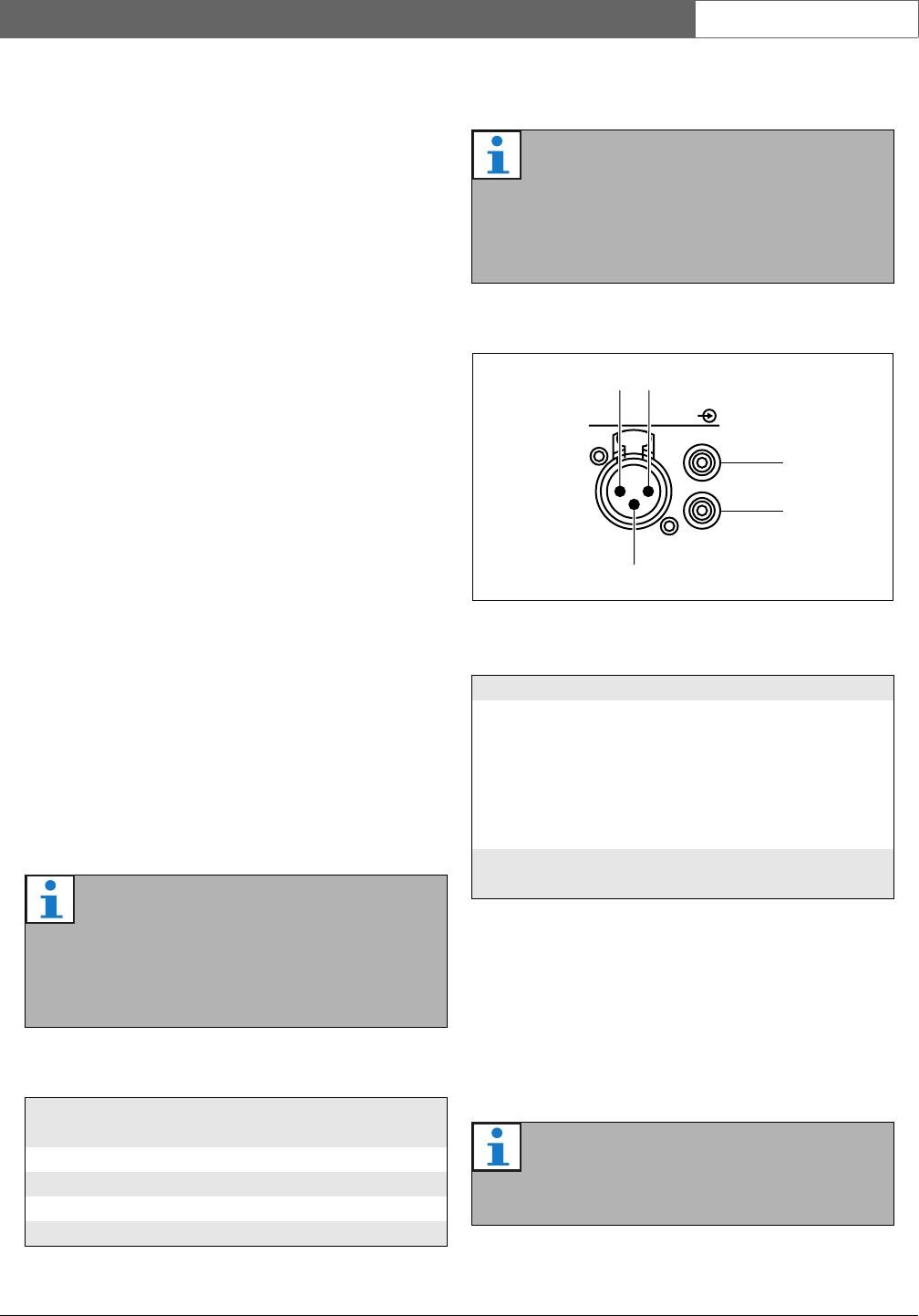
See figure 6.3 for details about the audio input sockets
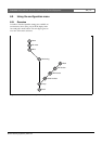
6.3.4 Connecting audio outputs
The audio expander has 4 audio outputs to route analog
audio signals to other equipment (e.g. a tape deck to
record a specific audio signal). Each audio output has
two connectors on the rear of the audio expander; one
XLR connector (for balanced signals) and one double
cinch connector (for unbalanced signals).
Note
The microphone inputs should not be used to
connect emergency microphones. These inputs
do not provide microphone connection
supervision.
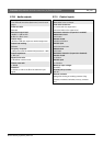
table 6.1: Audio input types
Audio Input Microphone
(XLR only)
Line
1Yes Yes
2 Yes Yes
3No Yes
4 No Ye s
Note
The audio inputs can handle electret
microphones as well as dynamic microphones,
since the audio expander can generate the
phantom supply for electret microphones.
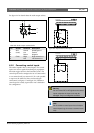
figure 6.3: Audio input sockets
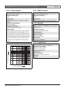
table 6.2: Audio input socket details
Pin Socket Definition Description
1 XLR
(female)
Xternal Shield/ground
(phantom supply -)
2 Live Positive
(phantom supply +)
3 Return Negative
(phantom supply +)
4 Cinch Right Right channel in
5 Left Left channel in
Note
The right and left cinch connectors carry the
same mono signal.
Audio In
2
3
1
5
4