


Bosch Security Systems | 2011-02
2011-02 | Installation and User Instructions | 5 | Call Stations en | 219
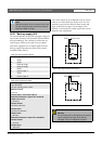
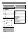
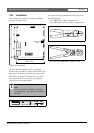
18.2.2 Headset (X11)
The external interface for headsets consists of a pin
header connector with 6 positions (see the PCB for the
pin numbering).
Note
Do not combine control input wires of multiple
control inputs (e.g. do not use a common return
wire).
table 18.3: X11 connector details
Pin Signal
1Mic
2 GND
3 Volume control voltage
4 3.3 V supply output
5GND
6 Earphone
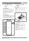
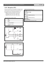
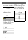
figure 18.5: Headset connection diagram
Note
The linear resistor R (typical value: 10 kohm) is
used to create a control voltage from the supply
voltage.
Microphone
R
Earphone
Volume
Headset
1
2
3
4
5
6
Note
If a volume control is not needed, pin 2 and 3
must be connected to each other. The volume
level of the earphone is then at its maximum.
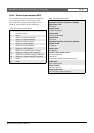
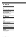
table 18.4: X11 technical data
Supervision limits for dynamic microphone:
180 to 1400 ohm
Mic. input sensitivity:
-50 dBV
Input sensitivity control range:
-7 to 8 dB
S/N:
60 dB +/- 3 dB at default sensitivity (mic.)
typical 80 dB +/- 3 dB (earphone)
Earphone impedance:
min. 16 ohm (typical 32 Ω)
Crosstalk (earphone to mic):
max. 40 dB ± 3 dB
Bandwidth:
340 to 14000 Hz
(-3 dB with respect to level at 1 kHz)
Output power:
0.1 to 30 mW (typical 1 mW)
Volume control voltage:
0 to 3.3 V