


Bosch Security Systems | 2011-02
2011-02 | Installation and User Instructions | 5 | Call Stations en | 252
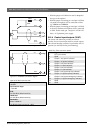
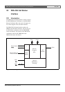
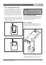
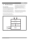
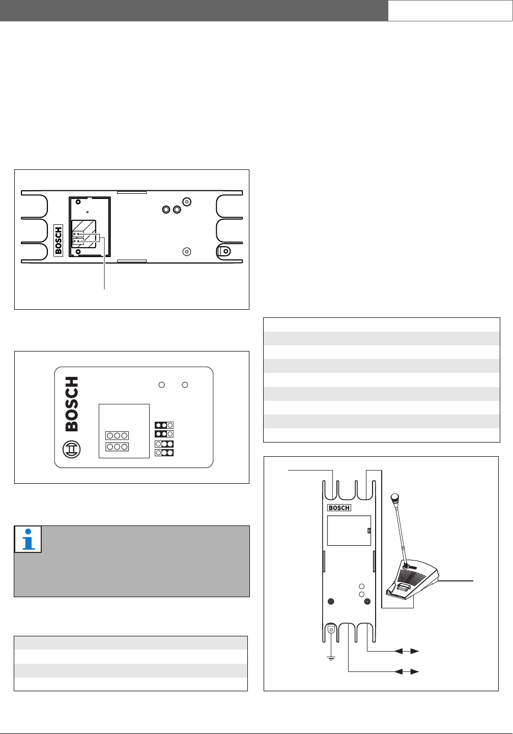
22.2.2 Interior
The interior of the call station interface (see figure 22.3
and figure 22.4) contains:
9 Power source - A set of jumpers that specify
whether the remote call station is powered via the
call station interface or uses its own external power
supply. See the label at the rear side of the lid for
information about the jumper settings..
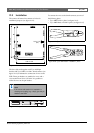
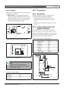
22.3 Connections
22.3.1 Introduction
This section gives an overview of typical system
connections using the call station interface:
• Connecting the network (see section 22.3.2).
• Connecting the remote call station (see section
22.3.2).
• Connecting an external power supply (see section
22.3.3).
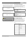
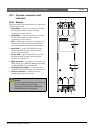
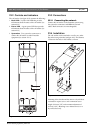
22.3.2 Connecting the network and
remote call stations
Use a straight Ethernet CAT-5 cable to connect a
remote call station to the call station interface, refer to
table 22.2 for the RJ45 pin definitions. For information
to connect the call station interface to the remote call
station and to the network refer to figure 22.5.
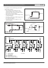
figure 22.3: Interior of the call station interface
figure 22.4: Jumper identification
Note
Make sure that the jumper settings are
compatible with the chosen power concept
(refer to section 22.3.3).
table 22.1: Jumper settings
Power supply Powerlink setting
Concept I Yes
Concept II Ye s
Concept III No
9
Fault Power
Ye s
No
Call Station
Powerlink
table 22.2 Pin definition of RJ45 interface
Pin Function Symbol
1 Power supply +48 V
2 Ground 0 V
3 Transmit + SX +
4 Receive + SR +
5 Receive - SR -
6 Transmit - SX -
7 Ground 0 V
8 Power supply +48 V
figure 22.5: Connecting the network and call stations
18-56 V(DC),
optional
76
12
Network
Network
18-56 V(DC),
optional
Ground