


Bosch Security Systems | 2011-02
Praesideo 3.5 | Installation and User Instructions | 6 | Installation Accessories en | 271
26.3 Connections
26.3.1 Introduction
This section gives an overview of typical system
connections using the fiber interface:
• Connecting the POF cable (see section 26.3.2).
• Connecting the GOF cable (see section 26.3.2).
• Connecting an external power supply
(see section 26.3.3).
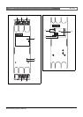
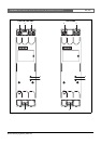
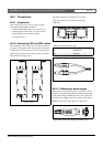
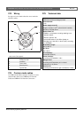
26.3.2 Connecting POF and GOF cables
Fiber interfaces convert from POF to GOF to connect
two pieces of equipment that are more than 50 m apart.
Usually, they are used in pairs. The first converts from
POF to GOF, whereas the second converts from GOF
back to POF (see figure 26.3).
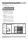
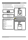
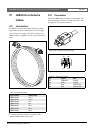
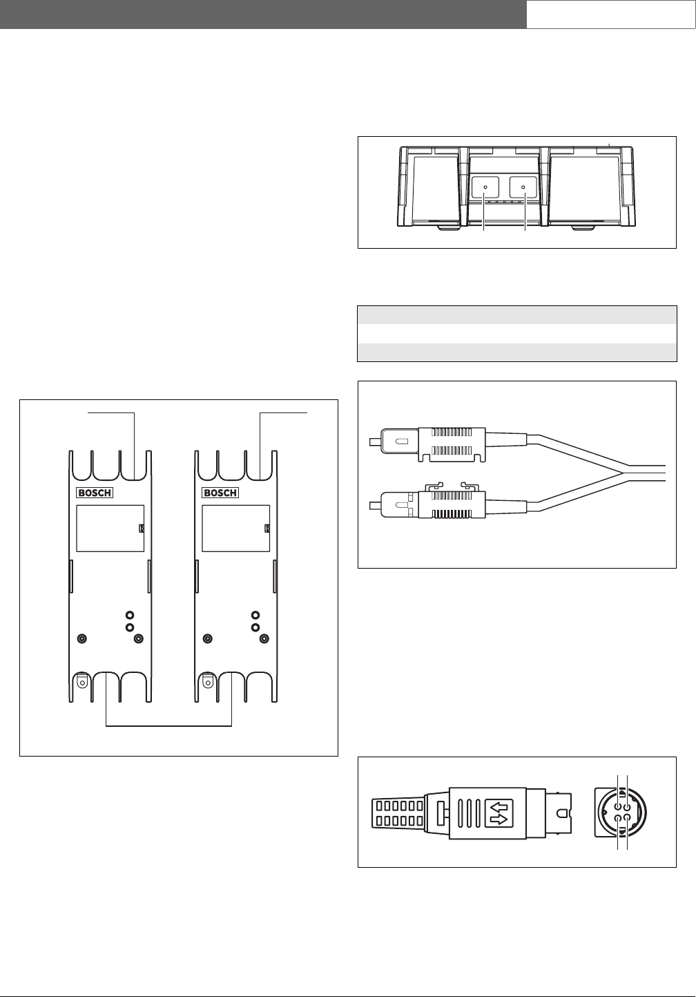
The GOF connector (see figure 26.4) is an SC
connector, which uses invisible infra-red light
(1300 nm).
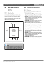
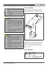
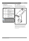
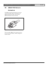
26.3.3 Connecting a power supply
This unit is powered by the network controller, via the
Praesideo system bus. But the fiber interface is delivered
with a separate Kycon KPP4-P connector to connect an
external power supply to the fiber interface. The Kycon
KPP-4P connector has four pins (see figure 26.6):
figure 26.3: Connecting the fiber interface
POF
GOF ( > 50m)
POF
33
77
figure 26.4: GOF connector
table 26.1: GOF connector pins
Pin Description
Tx Transmitter
Rx Receiver
figure 26.5: SC connector
figure 26.6: Connection diagram (external view)
Tx Rx
42
31