


Bosch Security Systems | 2011-02
Praesideo 3.5 | Installation and User Instructions | 3 | Control Equipment en | 88
5.3.4 Connecting the network
Connect the network controller to the Praesideo system
using the system bus connectors and LBB4416 network
cables. Both connectors are interchangeable.
5.3.5 Connecting a PC
5.3.5.1 Introduction
The network controller has one RJ45 socket to interface
with the Praesideo configuration PC. Using the
configuration PC, the Praesideo system can be
configured and diagnosed. Basically, there are two ways
to connect the configuration PC to the network
controller: directly (see section 5.3.5.3) or via a network
(see section 5.3.5.4).
5.3.5.2 Requirements
The configuration PC must meet the following
minimum requirements:
• Operating system:
Microsoft® Windows XP with Service Pack 1 or
Microsoft® Windows Vista or
Microsoft® Windows 7
• Network connection: 100 base-T
• 1 GB RAM
• Web browser installed, such as Internet Explorer of
Firefox
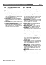
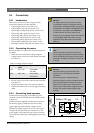
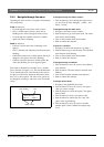
5.3.5.3 Direct connection
If the configuration PC must be connected directly to
the network controller, a crossover cable (Cat-5 cable)
must be used (see figure 5.5).
5.3.5.4 Via a network
If the configuration PC must be connected to the
network controller via a network, standard cables must
be used to connect both the network controller and the
configuration PC to the network.
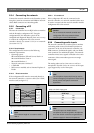
5.3.6 Connecting audio inputs
The network controller has 4 audio inputs to interface
with analog audio sources. Each audio input has two
connectors on the rear of the network controller; one
XLR connector (for balanced signals) and one double
cinch connector (for unbalanced signals). The network
controllers mixes stereo signals connected to the cinch
connectors of the same audio input into one single
mono signal.
The analog audio can be a line source as well as a
microphone. See table 5.2 for an overview of the input
types supported by each of the inputs.
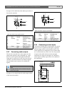
figure 5.5: Direct connection to PC
Note
The maximum length of a crossover-cable is
100 m.
TX+
RJ 45
(male)
Network Controller
RJ 45
(male)
PC
TX-
RX+
no sig.
no sig.
RX-
no sig.
no sig.
TX+
TX-
RX+
no sig.
no sig.
RX-
no sig.
no sig.
1
2
3
4
5
6
7
8
1
2
3
4
5
6
7
8
Caution
Do not connect the network controller and
configuration PC to any network without
consulting the network administrator.
Note
The microphone inputs should not be used to
connect emergency microphones. These inputs
do not provide microphone connection
supervision.
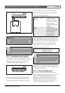
table 5.2: Audio input types
Audio Input Microphone
(XLR only)
Line
1YesYes
2 Ye s Yes
3NoYes
4 No Yes
Note
The audio inputs can handle electret
microphones as well as dynamic microphones,
since the network controller can generate the
phantom supply for electret microphones.