


Bosch Security Systems | 2011-02
2011-02 | Installation and User Instructions | 5 | Call Stations en | 241
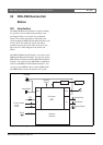
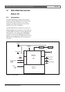
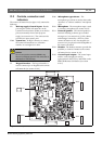
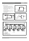
21.2 Controls, connectors and
indicators
The remote call station kit (see figure 21.2) contains the
following:
X2 Back-up supply/Control inputs - Besides
powering the remote call station kit via the
system network connector (X908), it can also be
powered externally from a back-up power
supply (see section 21.2.1). The connector also
provides two input contact pairs.
X908 System bus - An RJ45 connector to connect
the remote call station kit to a call station
interface via a straight Cat-5 cable.
X1 Keypad interface - The keypad interface is
used to connect up to 16 keypads to the remote
call station kit (see section 21.2.6).
X300 Microphone type selector - The
microphone type selector is used to select either
“dynamic” or “electret condenser” microphone
types.
X301 Microphone - The microphone input is used
to connect a microphone (see section 21.2.3).
X511 External Speaker - The external speaker is
meant for listening to chimes, pre-recorded
messages etc. (see section 21.2.5). Only chimes
and messages activated by a PTT key of the
remote call station or one of its keypads (see
section 47.3.3) are played via the loudspeaker of
the remote call station.
X501 Headset - The headset connector provides the
possibility to connect a headset to the remote
call station kit (see section 21.2.2).
X107 Control input/outputs - The control input
and five control outputs are used as
replacement for the PTT key and LEDs on the
PRS-CSR Remote Call Station (see section
21.2.4).
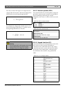
Caution
Do not connect the connector X908 to any
Telecom or Ethernet network. This connection is
dedicated for PRS-CSI only.
figure 21.2: Component side
8
1
.
.
.
.
.
X908
X2
X301
X107
1
6
.
.
.
.
.
X511
6
1
.
.
.
.
.
X501
6
1
.
.
.
.
.
X1
16
15
2
1
..
..
..
..
..
..
..
1
2
13
14
..
..
..
..
..
..
..
8
7
2
1
..
..
X300
1
3
.