


Bosch Security Systems | 2011-02
Praesideo 3.5 | Installation and User Instructions | 4 | Amplifiers en | 162
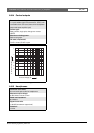
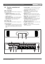
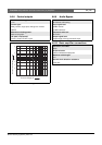
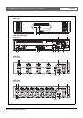
9.3.6 Connecting control outputs
The multi channel interface has 16 control outputs. The
control outputs can be used to send signals to third party
equipment to trigger actions. Each control output
connection has three pins (see figure 9.8).
The common (C) pin of the control output should
always be connected. Whether the other pin that is
connected is the normally closed (NC) or normally
open (NO) depends on the required action (see table
9.2).
In the configuration, a function must be assigned to the
control output that indicates when it becomes active (see
table 43.6).
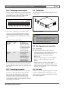
9.3.7 Connecting the ground
Connect the ground connection of the unit (see figure
9.2) to the 19- inch rack, which is connected to the
safety ground. For good resistance to electrostatic
discharges (ESD), it is important that the ground
connections of the multi channel interface and the
connected basic amplifiers are interconnected with short
wires, directly or via the rack.
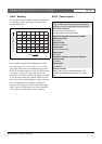
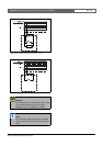
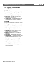
9.4 Installation
The multi channel interface is suitable only for 19-inch
rack installation.
9.5 Configuration and operation
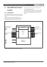
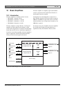
9.5.1 Overview
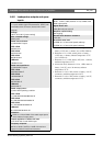
The multi channel interface has these functions:
• Changes the Bypass mode to Normal mode after the
multi channel interface starts. Refer to 9.5.2.
• Monitors the status of each basic amplifier.
Refer to 9.5.3.
• Monitors the power supply to the basic amplifiers.
• Monitors the line and loudspeaker supervision
devices.
• Makes the decision to make a spare amplifier
available if an amplifier channel fails. Refer to 9.5.3
• Changes the basic amplifier to Power saving mode if
necessary. See chapter 44.
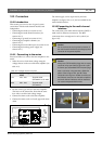
9.5.2 Fail safe
In default or unpowered state, the Bypass In is switched
to the basic amplifier channels. After power on and
when the network is present, the multi channel interface
goes to normal operation.
figure 9.8: Control outputs
table 9.2: Control outputs details
Connection Abbr. Description
Normally
closed
NC By default, the NC
contact is connected
with common contact
C. When the output is
activated, the NC
contact is opened.
Normally
open
NO By default, the NO
contact is not
connected with
common contact C.
When the output is
activated, the NO
contact is closed.
C
NC NO
C
NC NO
C
NC NO
C
NC NO
C
NC NO
C
NC NO
C
NC NO
C
NC NO
Control Out
12 34 5678
figure 9.9: Installation
Caution
When mounting the brackets to the unit, use the
screws that are supplied with the brackets.
Screws with a length of >10 mm may touch or
damage internal parts of the unit.