


Bosch Security Systems | 2011-02
2011-02 | Installation and User Instructions | 5 | Call Stations en | 230
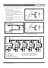
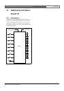
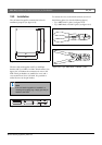
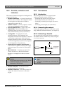
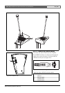
19.2.3 Keypad interface (X5, X6)
The external interface for connecting the keypad to
other keypads or to a (remote) call station consists of a
IDC connector with 16 positions (see the PCB for the
pin numbering). Keypads are connected in series to a
call station. This means that there is only a direct
connection between the call station and the first keypad.
The second keypad is connected to the first, the third to
the second etc. using standard flat cables.
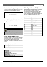
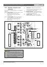
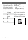
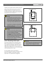
19.2.4 ID selector (S9)
It is possible to connect:
• Up to 16 call station keypads for pre-configured
actions (LBB4432/00 or LBB4434/00) to a (remote)
call station.
• Up to 15 call station keypads for pre-configured
actions (LBB4432/00 or LBB4434/00) and one
numeric keypad (PRS-CSNKP) to a (remote) call
station.
For a correct communication between the call station
and its keypads, the correct ID must be assigned to each
keypad for pre-configured actions using the ID selector
(see figure 19.2, no. S9 and figure 19.7).
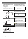
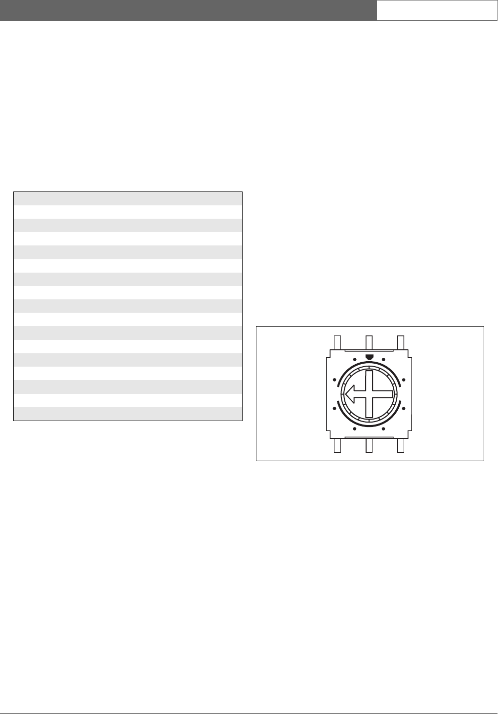
The ID of a keypad for pre-configured actions depends
on its position in the array of keypads. The first keypad
for pre-configured actions has ID 0, the next 1, and so
on up to F for the sixteenth keypad for pre-configured
actions.
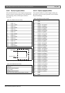
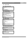
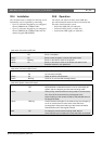
table 19.5: X5 and X6 connector details
Pin Signal
1 Synchronization line.
2 GND
3 Interrupt line (INT)
4 GND
5 Data I2C (SDA)
6 GND
7 Clock I2C (SCL)
8 GND
9Power
10 GND
11 Po we r
12 GND
13 Power
14 GND
15 Power
16 GND
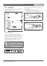
figure 19.7: ID selector
2E
6A
8
C4