


Bosch Security Systems | 2011-02
2011-02 | Installation and User Instructions | 5 | Call Stations en | 220
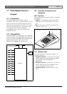
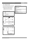
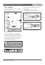
18.2.3 Microphone (X70)
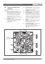
The external interface for microphones consists of a pin
header connector with 6 positions (see the PCB for the
pin numbering). The following microphones were
designed to be used in combination with the kit:
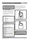
• LBB9081 Hand-held Dynamic Microphone
(including resistors for switch supervision).
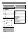
• LBB9082 Gooseneck Dynamic Microphone.
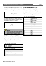
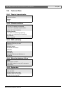
table 18.5: X70 connector details
Pin Signal
1Mic-
2 GND
3Mic+
4 --- not connected ---
5 PTT input contact
6 GND
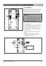
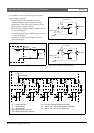
figure 18.6: LBB9081 connection diagram
figure 18.7: LBB9082 connection diagram
10kΩ
10kΩ
blue
black
red
white
black
(thick)
5
6
3
1
2
1
3
2
black
white
red
table 18.6: X70 technical data
Microphone input sensitivity:
-50 dBV
Input control range:
-7 to 8 dB
S/N:
min. 60 dB at default sensitivity
Headroom:
min. 30 dB at default sensitivity
Bandwidth:
340 to 14000 Hz
(-3 dB with respect to level at 1 kHz)