


Bosch Security Systems | 2011-02
Praesideo 3.5 | Installation and User Instructions | 7 | System Hardware Installation en | 303
controller. The standard EN 54-16 requires a minimum
sound pressure level of 60 dB for the voice alarm
condition and 50 dB for the fault warning condition, on
1 m distance, even with the door of the rack closed.
The Praesideo PRS-NCO-B is delivered with a suitable
buzzer for these purposes. This buzzer needs a power
supply with backup. Although the system network
supply could be used for this purpose, the power supply
lines of the hybrid network cable are not easily
accessible. Another option is to use the RS232
service-connection on the rear of the network controller.
This connection is never used in an installed system, so
it is possible to take advanrtage of its availability. An
output voltage is available on pin 6 (DTR output) that
switches between -9V and +9V, while pin 5 provides a
GND connection. Using a high efficiency buzzer and a
rectifier bridge, the RS232 connection can provide
enough power to drive the buzzer to the required sound
pressure level. Control outputs are located on short
distance of the RS232 connector, to provide the
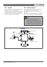
switching information. See the wiring diagram in figure
32.5.
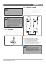
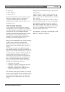
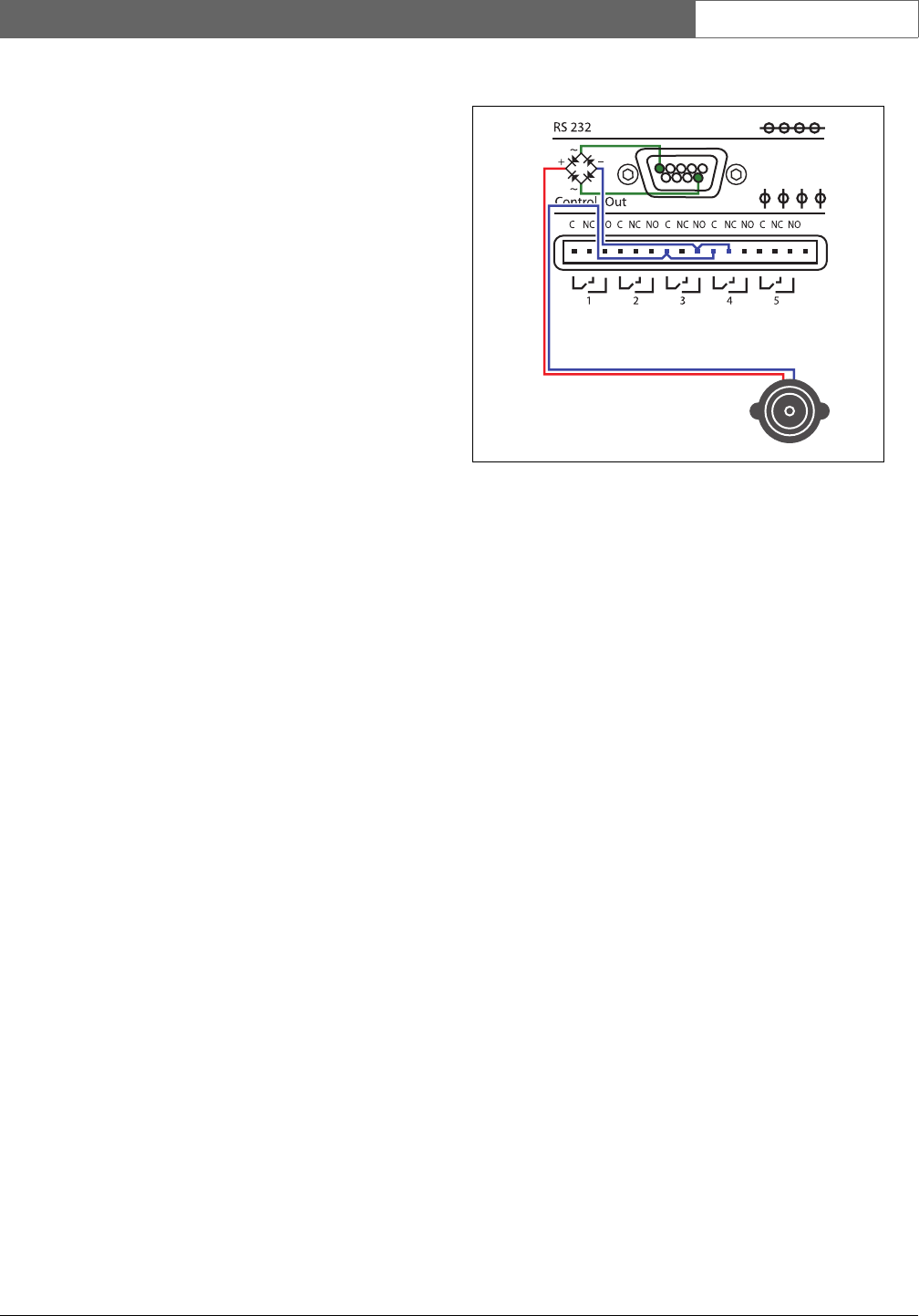
In this arrangement, the voltage between the RS232
DTR and GND connections is rectified and wired to the
buzzer. The negative lead is interrupted by control
outputs 3 and 4, connected in parallel, configured as
follows:
• NCO_CO4 is enabled and configured as Fault alarm
buzzer (by default, cannot be changed, see section
43.2.6)
• NCO_CO3 is enabled and configured as Emergency
alarm buzzer (see section 43.2.6)
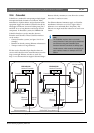
NCO_CO3 and NCO_CO4 are connected in parallel.
The C-terminals of both control outputs are
interconnected and the NO-terminal of NCO_CO3 is
connected to the NC-terminal of NCO_CO4 to switch
on the buzzer in case of an emergency alarm or fault
alarm. The NC-terminal of NCO_CO4 is used instead
of the NO-terminal because this control output is
operated in an opposite mode for fail safe reasons. The
unpowered (!) state represents the fault situation, as is
the case for NCO_CO5, the fixed control output for the
Fault alarm indicator.
The buzzer supplied with the network controller is
connected to an RS232 connector, with build-in rectifier
bridge, by means of a 2 m long cable. This allows the
buzzer to be positioned in the 19-inch rack, on such a
location that the required audio levels are attained. The
RS232 connector also provides a short control cable
that can be connected to the NCO_CO3 and
NCO_CO4 contacts, as shown in the figure.
figure 32.5: Connecting an alarm buzzer to the
network controller