


Bosch Security Systems | 2011-02
2011-02 | Installation and User Instructions | 5 | Call Stations en | 243
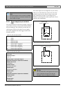
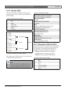
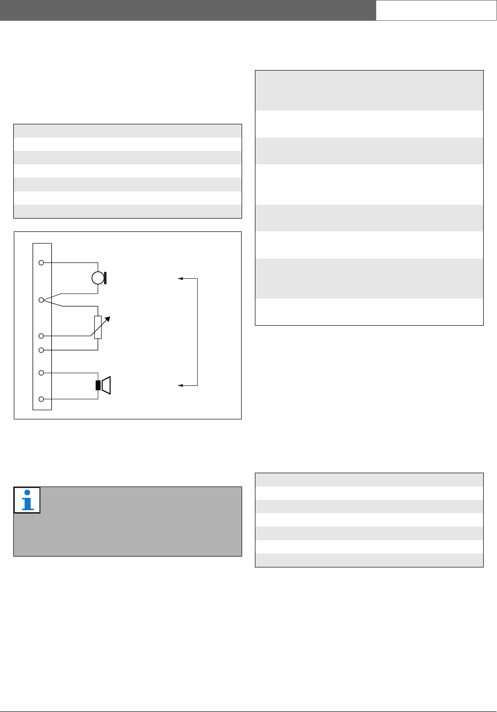
21.2.2 Headset (X501)
The external interface for headsets consists of a pin
header connector with 6 positions (see the PCB for the
pin numbering).
The volume control (R) between pins 2, 3 and 4 must be
a 10k logarithmic potentiometer.
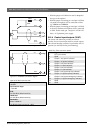
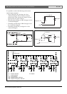
21.2.3 Microphone (X300 and X301)
The external interface for microphones consists of a pin
header connector with 6 positions (see the PCB for the
pin numbering). The following microphones were
designed to be used in combination with the kit:
• LBB9081 Hand-held Dynamic Microphone
(including resistors for switch supervision).
• LBB9082 Gooseneck Dynamic Microphone.
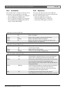
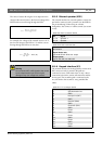
table 21.3: X501 connector details
Pin Signal
1Mic
2 GND
3 Volume out
4 Volume max. in
5GND
6 Earphone
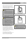
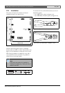
figure 21.5: Headset connection diagram
Note
If a volume control is not needed, pin 3 and 4
must be connected to each other. The volume
level of the earphone is then at its maximum.
Microphone
R
Earphone
Volume
Headset
1
2
3
4
5
6
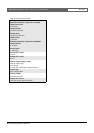
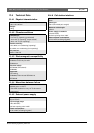
table 21.4: X501 technical data
Supervision limits:
180 to 1400 Ω (dynamic microphone)
0.2 to 4.8 mA (electret microphone)
Mic. input sensitivity:
-50 dBV
Input sensitivity control range:
-7 to 8 dB
S/N:
60 dB +/- 3 dB at default sensitivity (mic.)
typical 80 dB +/- 3 dB (earphone)
Earphone impedance:
min. 16 ohm (typical 32 ohm)
Crosstalk (earphone to mic):
max. 40 dB ± 3 dB
Bandwidth:
340 to 14000 Hz
(-3 dB with respect to level at 1 kHz)
Output power:
0.1 to 30 mW (typical 1 mW)
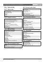
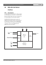
table 21.5: X301 connector details
Pin Signal
1Mic-
2 GND
3Mic+
4 --- not connected ---
5 PTT input contact
6 GND