


Bosch Security Systems | 2011-02
Praesideo 3.5 | Installation and User Instructions | 6 | Installation Accessories en | 269
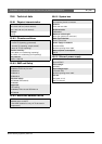
26 PRS-FIN, PRS-FINNA,
PRS-FINS Fiber Interface
26.1 Introduction
The PRS-FIN, PRS-FINNA or PRS-FINS Fiber
Interfaces are used to convert from plastic optical fiber
(POF) cable to glass optical fiber (GOF) cable and vice
versa for covering long distances. The following types
are available:
The PRS-FINNA Fiber Interface only converts from
POF to GOF. It does not count as a node in the system
(see table 31.2) with respect to the maximum number of
nodes, 63, that can be in a system. It is intended for
systems in which otherwise the maximum number of
nodes would be exceeded. However, this unit does
influence the maximum cable length of the system as if
it was a normal node (see figure 31.5).
In emergency sound systems, do not use this type of
fiber interface to power far-end units. Since it does not
have any control inputs, it is not possible to supervise its
external power supply (if connected). Using the
PRS-FINNA Fiber Interface as a near-end fiber interface
that is connected to the network controller is possible
though.
These units in metal housing are the successors of the
LBB4414/00, LBB4414/10 and PRS-FINMO in plastic
housing.
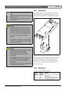
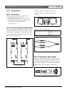
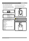
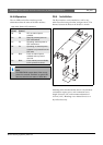
26.2 Controls, connectors and
indicators
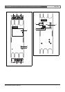
The fiber interface (see figure 26.2) contains the
following:
1 External power supply - A connection for an
(optional) external power supply. The external power
supply feeds the Praesideo network (see section
26.3.3).
2 Control inputs - The control inputs can be used to
receive signals from third party equipment that must
trigger actions in the Praesideo network (see
section 26.3.4).
3 POF connector - A POF connector to connect the
fiber interface to a POF cable (see section 26.3.2).
4 Power LED - A green power LED that provides
information about the status of the fiber interface.
(see section 26.3.5).
5 Fault LED - A yellow fault LED that provides
information about the status of the fiber interface
(see section 26.3.5).
6 GOF connector - A GOF connector to connect
the fiber interface a GOF cable (see section 26.3.2).
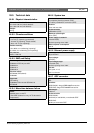
Type Description
PRS-FIN Fiber Interface with control inputs
(multi mode)
PRS-FINNA Fiber Interface without control inputs
(multi mode)
PRS-FINS Fiber Interface with control inputs
(single mode)
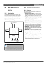
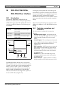
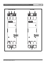
figure 26.1: Block diagram of the fiber interface
Network
Processor
POF
Control Inputs
GOF
Fault
I
Power External
Power