


Bosch Security Systems | 2011-02
Praesideo 3.5 | Installation and User Instructions | 6 | Installation Accessories en | 282
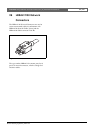
29.4 Cable-connector installation
29.4.1 Introduction
This chapter contains a step-by-step description of the
cable-connector installation process. The procedure
consists of the following parts:
• Preparation (see section 29.4.3).
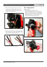
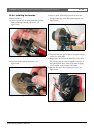
• Crimping the bush (see section 29.4.4).
• Stripping the copper wires (see section 29.4.5).
• Installing the socket contacts (see section 29.4.6).
• Stripping the optical fibers (see section 29.4.7).
• Installing the ferrules (see section 29.4.8).
• Assembling the connector (see section 29.4.9).
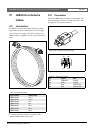
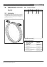
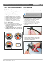
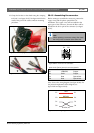
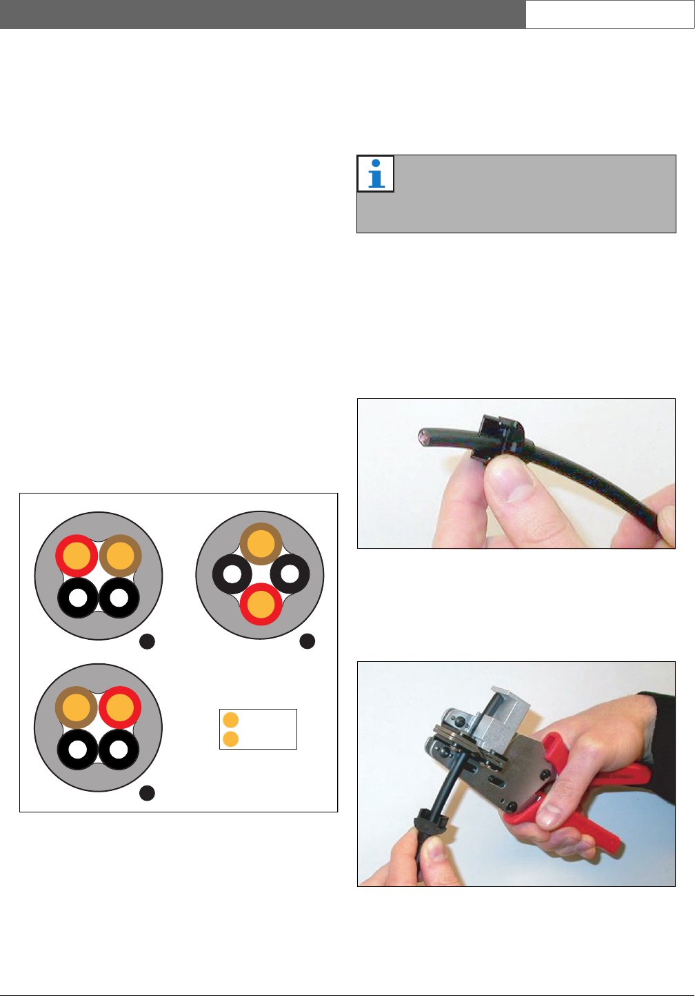
29.4.2 Cable types
There are two types of optical network cables:
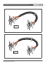
• Type A cables in which the plastic optical fibers are
located next to each other (see figure 29.5, which
shows both cable ends).
• Type B cables in which the plastic optical fibers are
located opposite to each other (see figure 29.5, both
cable ends are identical).
29.4.3 Preparation
Proceed as follows:
1 Cut the optical network cable to the required length
using the cable cutter (tool 2).
2 Determine the cable type (see section 29.4.2), since
some steps in the cable-connector installation
procedure depend on the cable type.
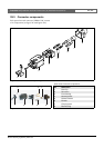
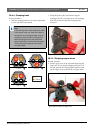
3 Disassemble a network connector. A network
connector consists of 10 parts (see section 29.3).
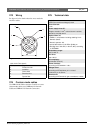
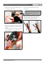
4 Slide the back housing over the cable (see
figure 29.6).
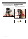
5 Using the stripping tool (tool 5), strip the outer
sheath of the cable by pushing the cable to the
mechanical stop (see figure 29.7).
figure 29.5: Cable types
A
B
A
B
B
R
= Red
= Brown
R
R
B
R
B
Note
Due to light loss, the length of an optical
network cable must be less than 50 m.
figure 29.6: Back housing on cable
figure 29.7: Stripping the cable